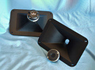
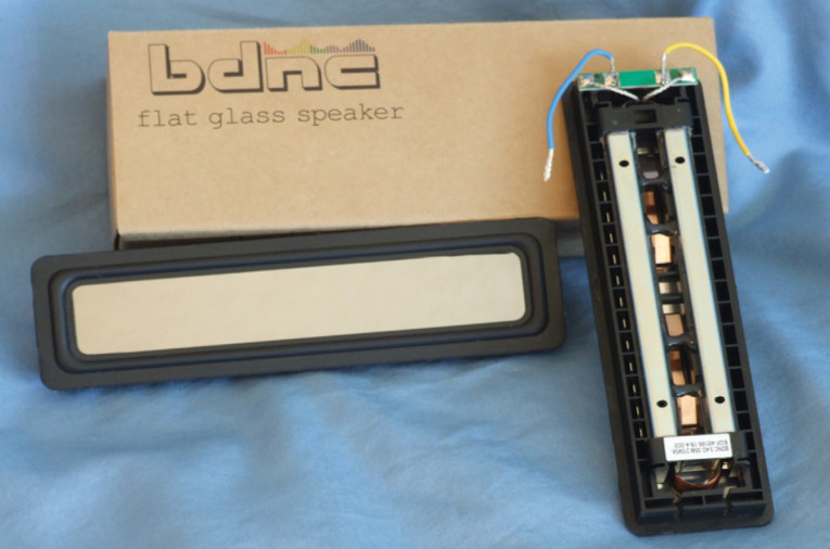
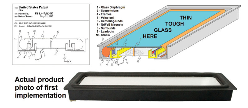
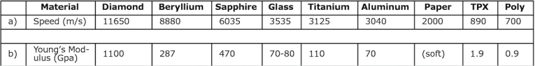
The transducer that BDNC sent for Test Bench is a glass cone “race track” shaped device, the BGF-46166-18-4-003 (Photo 1). This driver is covered by US Patent Number 8,447,063 titled, “Flat Dynamic Speaker.” A cutaway of the original patented concept is depicted in Figure 1, with a close-up image of the back of the driver shown in Photo 2. This is a flat diaphragm cone that measures 14cm × 2.4cm (5.56” × 0.95”) and its claim to fame is that it is the first glass diaphragm transducer to be produced (BDNC also makes a 40mm diameter glass cone driver, the BGC-D40-22-4-002). Table 1 provides a comparative analysis of speed of sound, and Young’s Modulus supplied by BDNC of various loudspeaker diaphragm materials and glass.
The glass diaphragm is a composite made up of two layers of “Schott AS87 Glass” with an internal layer of viscoelastomic damping material and aluminum alloy foil. This composite flat diaphragm has a total thickness of 0.3mm and mass of 3.4g, and looks visually like a high-quality mirror.
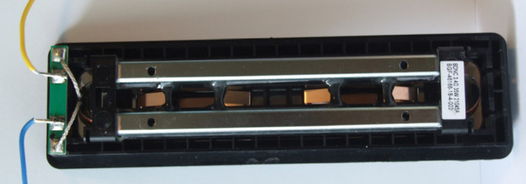
Suspension for the glass diaphragm is provided by a small NBR (CBR) surround, and two metal leaf springs that are visible in Photo 2, glued to an injection-molded plastic frame. The motor structure is comprised of two neodymium bar magnets surrounded by a steel return cup that forms a gap area. This drives a 13.5cm × 1.5cm two-layer race track-shaped voice coil wound with round copper wire on an aluminum former glued directly to the glass diaphragm. Tinsel leads are soldered to a pair of circuit board solder pads located at one end of the frame.
I began testing the BGF-46166-18-4-003 full-range flat diaphragm driver using the LinearX LMS analyzer and the Physical LAB IMP Box to create both voltage and admittance (current) curves with the driver clamped to a rigid test fixture in free-air at 0.3V, 1V, 3V, 6V, and 10V, with the oscillator on time between sweeps to simulate the actual thermal process over time. The 10V curves were too nonlinear to get a sufficient curve fit and were discarded.
Following my established protocol for Test Bench testing, I no longer use a single added mass measurement and instead use the physically measured Mmd data (17.8 grams for the BGF-46166-18-4-003). The collected data, in this case the eight 550-point (0.3V to 6V) sine wave sweeps for each BDNC sample, were post-processed and the voltage curves divided by the current curves to generate impedance curves, with the phase derived using the LMS calculation method. I imported the data, along with the accompanying voltage curves, to the LEAP 5 Enclosure Shop software.
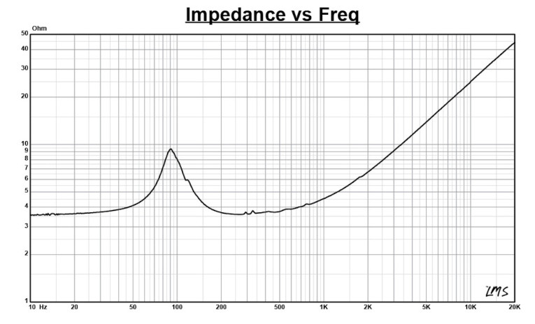
Figure 2 shows the 1V free-air impedance curve. I selected the 1V TSL data in the transducer parameter derivation menu in LEAP 5 and created the parameters for the computer box simulations. Table 2 compares the LEAP 5 LTD/TSL TSP data and factory parameters for both of the BGF-46166-18-4-003 samples.
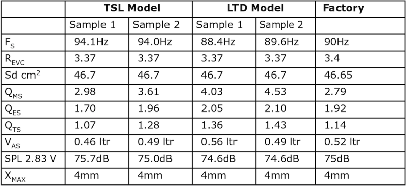
LEAP LTD and TSL parameter calculation results for the BGF-46166-18-4-003 correlate reasonably well with the factory published data. Once again, I followed my established protocol and set up computer enclosure simulations using the LEAP TSL parameters for Sample 1. As it turned out, with this high a Qts, the best enclosure solution is to just put the transducer in a large enough enclosure not to drive the Qts any higher. Lowering it to any reasonable value like Qtc = 0.9 to 0.7 requires an impractically large enclosure short or an infinite baffle. That said, I simulated the BGF-46166-18-4-003 in a 0.1 ft3 simulated sealed box enclosure with Qtc = 1.14, equal to the free-air Qts of the driver.
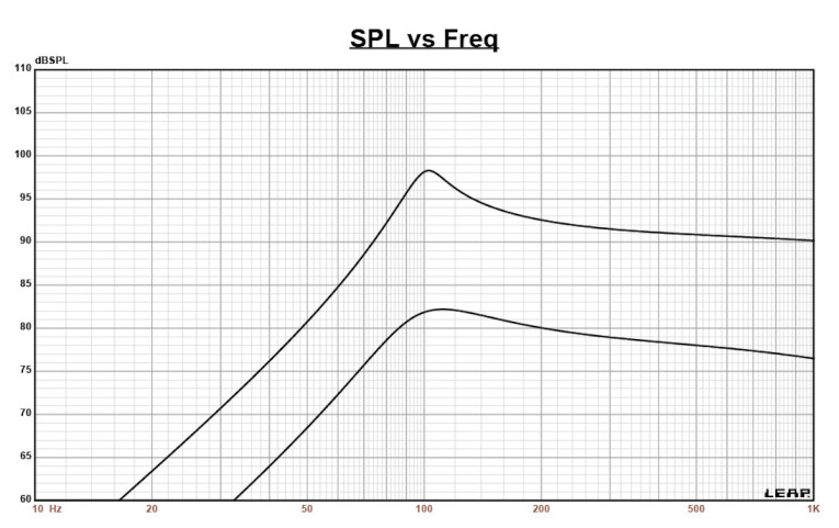
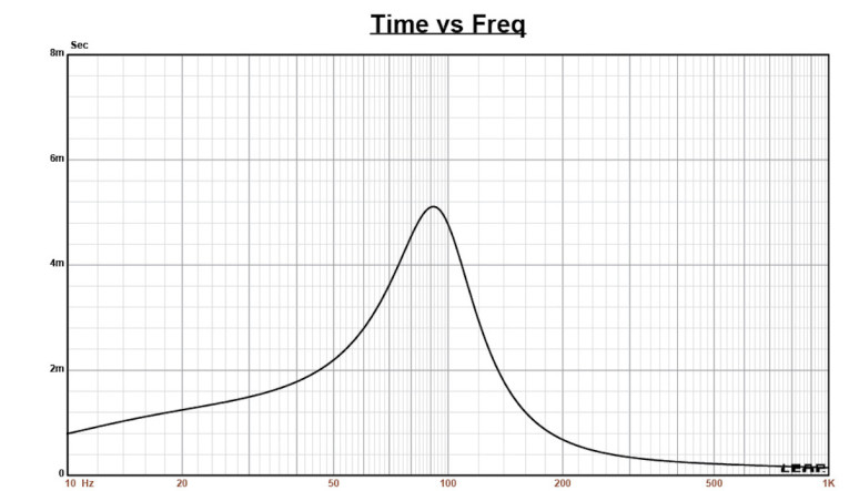
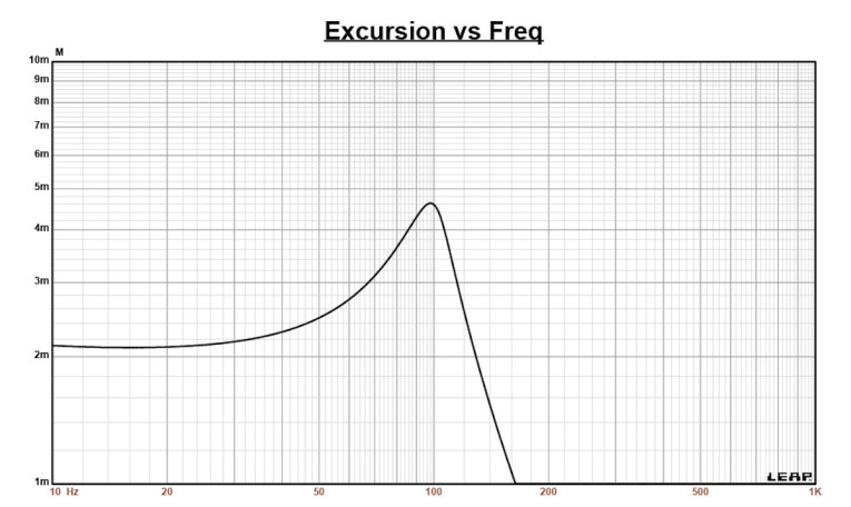
Figure 3 displays the box simulation results for the BGF-46166-18-4-003 in the sealed enclosures at 2.83V and at a voltage level that achieves and excursion level equal to Xmax + 15% (4.6mm for the BGF-46166-18-4-003). This resulted in a F3 of 82Hz (-6dB = 72Hz) with a Qtc = 1.14. Increasing the voltage input to the simulation until Xmax + 15% excursion level was reached resulted in 98.2dB at 19V for the sealed enclosure simulation. Figure 4 shows the 2.83V group delay curve. Figure 5 shows the 19V excursion curve.
Klippel analysis for the BGF-46166-18-4-003, which this month was performed by Jason Cochrane from Warkwyn (the US purveyor of Klippel GmbH products), using the Klippel KA3 analyzer. The analysis produced the Klippel data graphs shown in Figures 6-9. The Bl(X) curve shown in Figure 6 is difficult to interpret as it did not resolve into any shape that would lead to any specific conclusion about its piston range performance. The Bl symmetry curve shown in Figure 7 also was unable to resolve in any meaningful way to be able to draw any performance conclusions, this may suggest some rocking issues, but again, there is not enough information upon which to draw a conclusion.
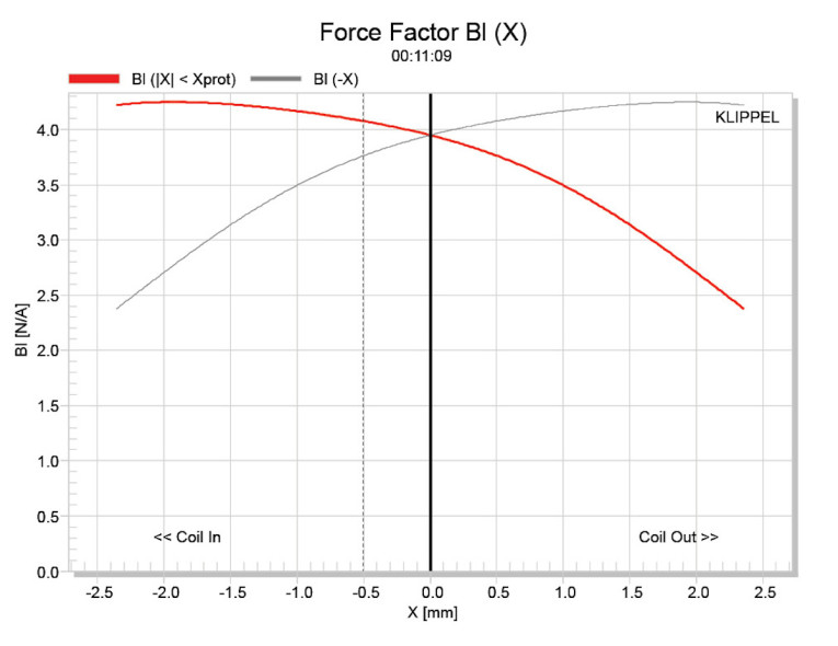
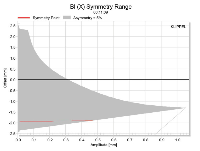
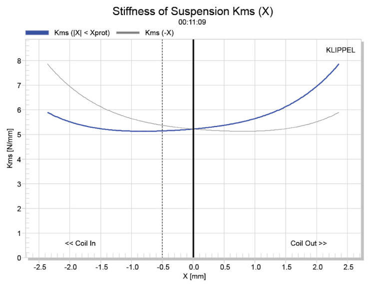
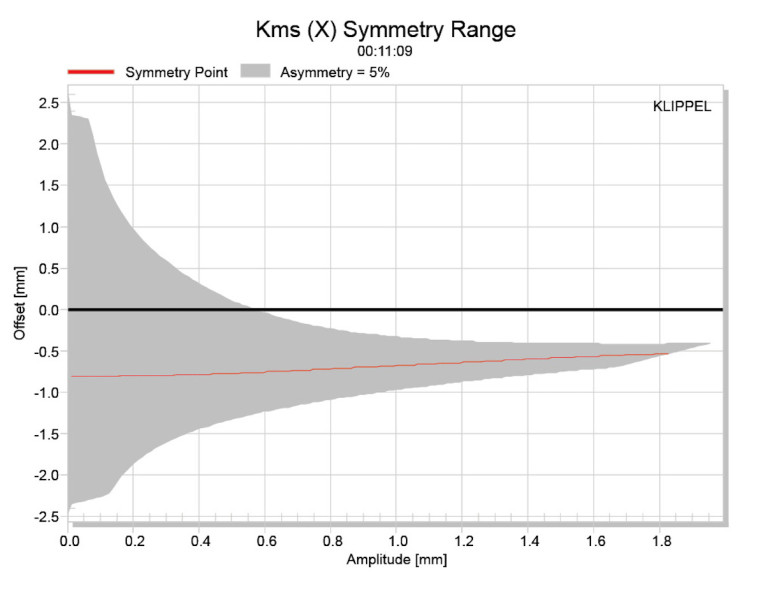
Figure 8 and Figure 9 show the Kms(X) and the Kms symmetry curves for the BGF-46166-18-4-003 driver. The Kms Stiffness of Compliance curve shown in Figure 8 appears asymmetrical with a degree of rearward (coil-in) offset, but once again the analyzer was not able to resolve much past 2mm and this driver has an Xmax of 4mm. The Kms symmetry range curve shown in Figure 9 exhibits a 0.6mm coil-in (rearward) offset that is decreasing at about 1.5mm, but again the analyzer was not able to resolve the data even up to 2mm.
Obviously, this is an unusual motor format, and unfortunately I cannot say anything specific about the data because the operational aspect of this driver was not able to be resolved in any meaningful way. That said, using the BGF-46166-18-4-003 in its piston range is probably best determined empirically. This also does not preclude using this driver as a midrange from 200Hz and up, where, the BGF-46166-18-4-003 exhibits outstanding off-axis performance in the horizontal plane.
The BGF-46166-18-4-003’s displacement limiting numbers calculated by the Klippel analyzer using the full-range woofer’s criteria for Bl was XBl @ 82% (Bl dropping to 70% of its maximum value 1.37mm for the prescribed 10% distortion level. For the compliance, XC @ 75% Cms minimum was only 2.01mm, however since none of the data resolved much beyond 2mm, you really can’t make a conclusion from this data.
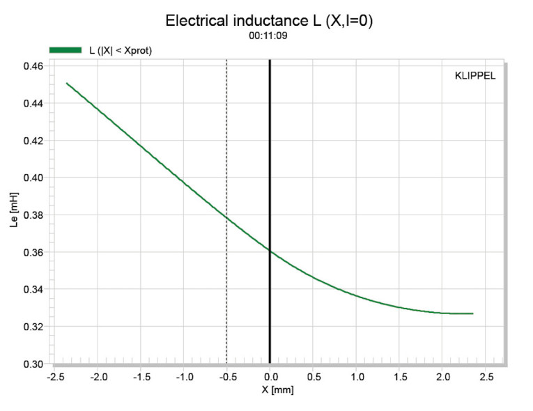
Figure 10 gives the inductance curve L(X) for this transducer. Motor inductance will typically increase in the rear direction from the zero rest position as the voice coil covers more of pole in a conventional motor, which is what you see in the graph. And even though the inductive swing looks fairly good, there is the same problem as the rest of the data—not being able to resolve out to and beyond the driver’s Xmax.
For the remaining test procedures, I mounted the
BGF-46166-18-4-003 in a foam-filled enclosure that had a 12” × 8” baffle and then measured the DUT using the LoudSoft FINE R+D analyzer and the GRAS 46BE microphone (courtesy of LoudSoft and GRAS Sound & Vibration) both on- and off-axis from 200Hz to 20kHz at 2.0V/0.5m, normalized to 2.83V/1m using the cosine windowed FFT method. All of these SPL measurements also included a 1/6 octave smoothing.
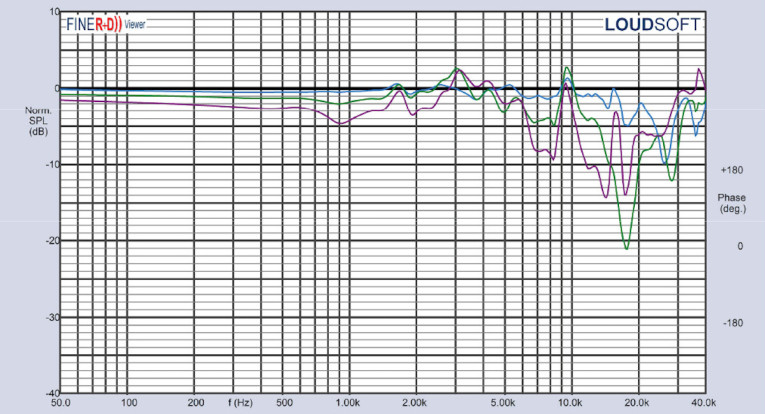
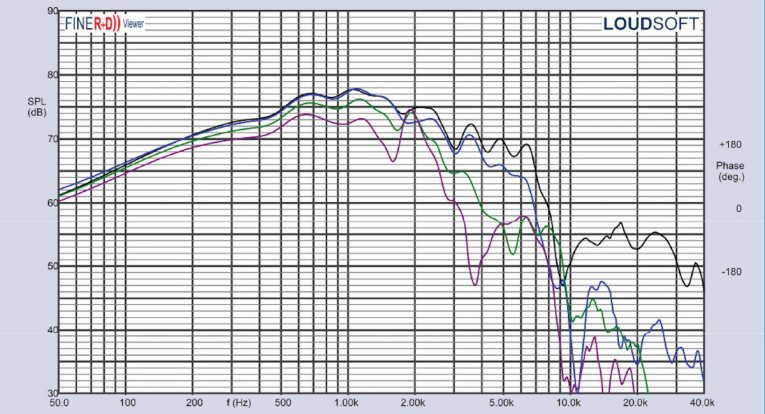
Figure 11 gives the BGF-46166-18-4-003’s on-axis response indicating a fairly smooth rising response with no break-up modes or peaking that is ±3dB from 250Hz to 2.8kHz, with response out to about 7kHz, where the driver begins its low-pass roll-off. Figure 12 displays the on- and off-axis frequency response at 0°, 15°, 30°, and 45° in the horizontal plane (with the driver oriented vertically), which is extremely good. The -3dB at 45° (not 30°) with respect to the on-axis curve occurs very high in frequency at 6kHz, so a cross point in that vicinity should be work well to achieve a good power response, although the driver would require some equalization between 2kHz to 6kHz.
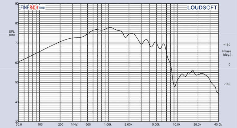
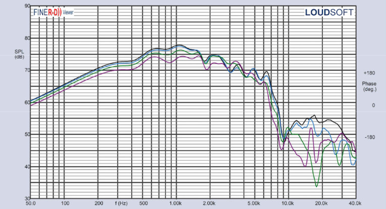
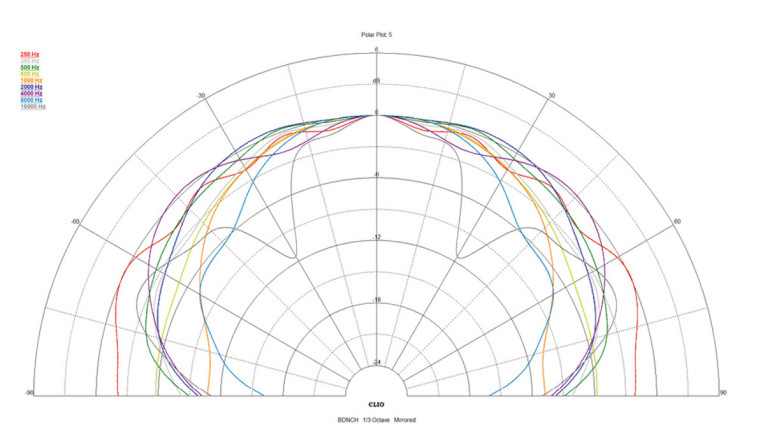
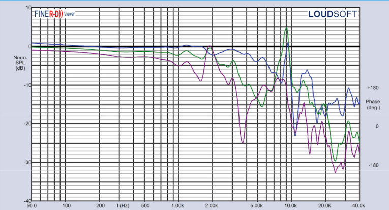
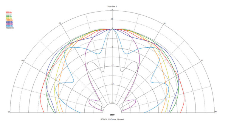
Figure 13 shows the normalized version of Figure 12. Figure 14 displays the CLIO horizontal polar plot (in 10° increments). Since the diaphragm is rectangular shaped, you would expect a degree of cancellation in the vertical plane, which is indeed the case. In the vertical plane, the 0° to 45° response is given in Figure 15, with the normalized version depicted in Figure 16, and the CLIO vertical polar plot given in Figure 17.
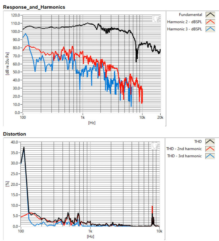
For the remaining series of tests, I again set up the Listen, Inc. SoundCheck AudioConnect analyzer and SCM microphone (graciously supplied by the folks at Listen, Inc.) to measure distortion and generate time frequency plots. For the distortion measurement, I mounted the BGF-46166-18-4-003 driver rigidly in free-air, and set the SPL to 84dB.
I would normally have set the SPL to 94dB, but given the sensitivity of this driver is about 10dB lower than most of the hi-fi drivers I test, I thought it was more appropriate to lower the SPL for distortion testing. The voltage required to achieve 84dB at 1m was set at 11.8V, using a SoundCheck pink noise stimulus. I then measured the distortion with the Listen microphone placed 10cm from the driver. This produced the distortion curves shown in Figure 18.
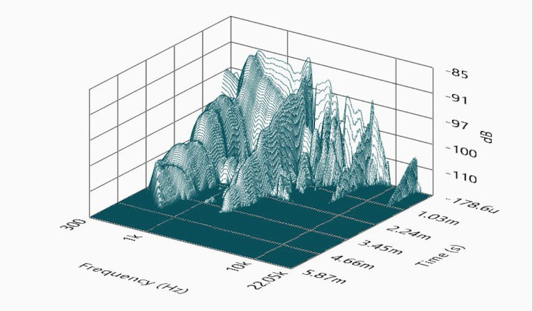
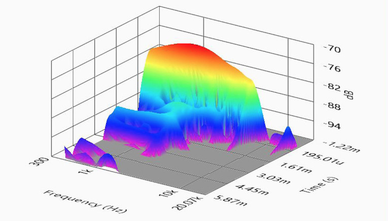
I next used the SoundCheck software to get a 2.83V/1m impulse response for this driver and imported the data into Listen’s SoundMap Time/Frequency software. Figure 19 shows the resulting CSD waterfall plot. Figure 20 shows the Wigner-Ville plot (chosen for its better low-frequency performance).
The BDNC is a very unique driver with some attributes that would suggest its use in multiples, such as a line array, that could produce excellent off-axis response and be highly effective. As I mentioned, BDNC also produces a 40mm glass cone speaker, which should also prove interesting. For more information, read this interesting article by Mike Klasco and visit www.newbdnc.com. VC
This article was originally published in Voice Coil, June 2021.