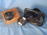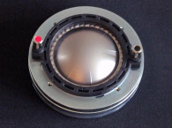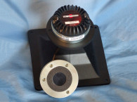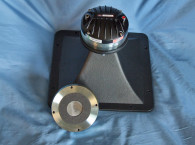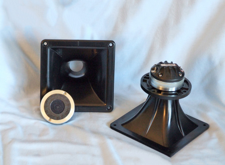
B&C Speakers’ also supplied its 1” throat 90 H × 60 V hyperbolic cosine flare injection-molded ABS ME10 horn with a 1.5-Hz cut-off frequency. (The new DE110-8 has a close-spaced two-hole mounting pattern that does not match any of the 1” horns in B&C Speakers’ horn line.) To use the ME10, I had to drill two mounting holes (the ME10 has a standard wide spaced four-hole mounting pattern). However, this is a quick and easy modification.
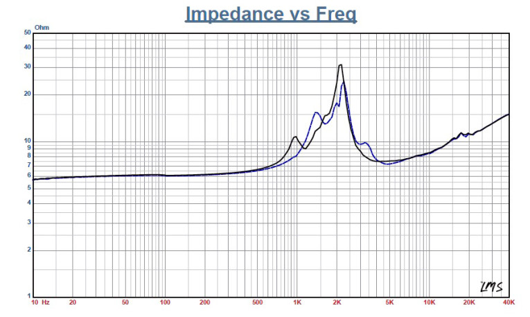
I used the LinearX LMS analyzer to produce the 300-point stepped sine wave impedance plot shown in Figure 1. The solid black curve represents the DE110 mounted on the ME100 horn and the dashed blue curve represents the compression driver without the horn. With a 6.25-Ω DCR, the DE110/ME10’s minimum impedance was 7.48 Ω at 4.2 kHz. Next, I free-air mounted the B&C DE110/ME10 without an enclosure and measured both the horizontal and vertical on and off axis at 2.83 V/1 m, using a 100-point gated sine wave sweep from 0° on axis to 60° off axis.
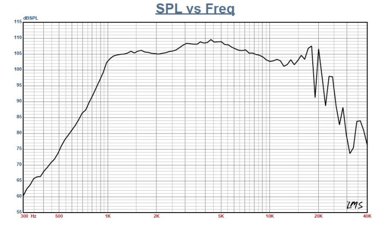
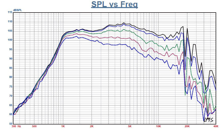
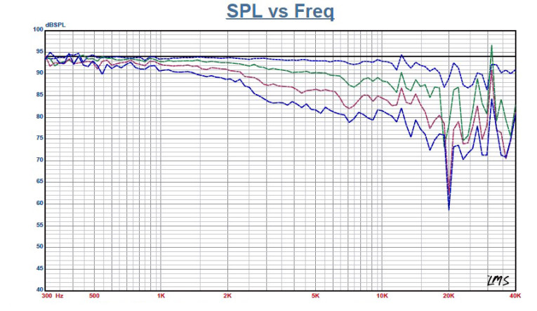
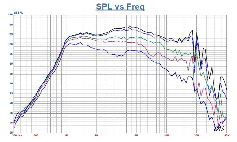
Figure 2 displays the on-axis frequency response of the compression driver/horn combination. The response was smooth with no major anomalies ±4 dB from 1.5 kHz out to18 kHz and a declining response as frequency increases above 5 kHz (±2 dB from 1.5 to 7.4 kHz). For the D110, B&C Speakers recommends a 1.5-kHz crossover frequency with a second-order or higher high-pass filter.
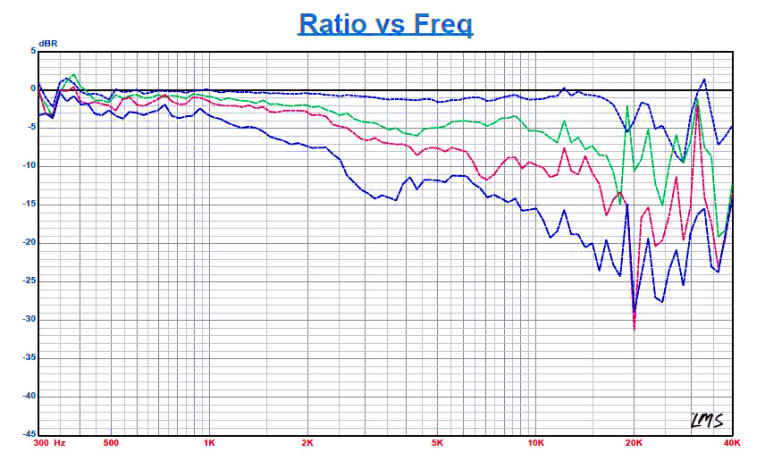
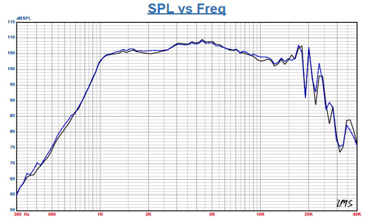
Figure 3 gives the on- and off-axis response in the horizontal plane. Figure 4 shows the normalized horizontal plane response. Figure 5 shows the on- and off-axis response in the vertical plane. Figure 6 shows the normalized vertical plane response. Last, Figure 7 has the two-sample SPL comparison showing the two DE110 compression driver samples to be closely matched.
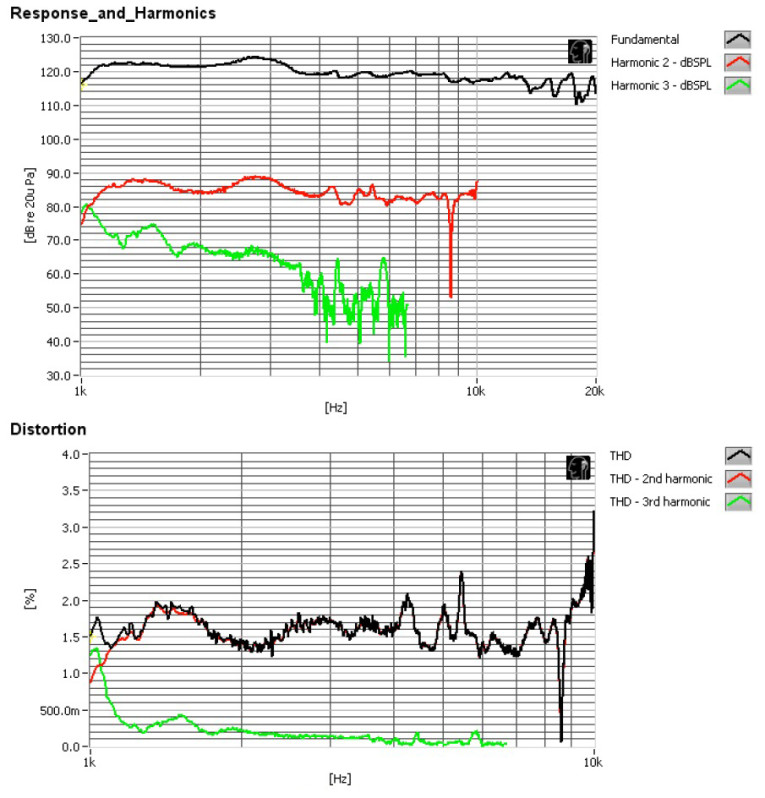
For the remaining tests, I fired up the Listen AmpConnect ISC analyzer, the 0.25” SCM microphone, and the power supply to measure distortion and generate time-frequency plots. For the distortion measurement, I mounted the B&C DE110/ME10 combination in free-air as I did to obtain the frequency response measurements. I set the SPL to 104 dB at 1 m (2.46 V, determined by using a pink noise stimulus generator and internal SLM in the SC12 software), and measured the distortion with the Listen microphone placed 10 cm from the horn’s mouth. This produced the distortion curves shown in Figure 8.
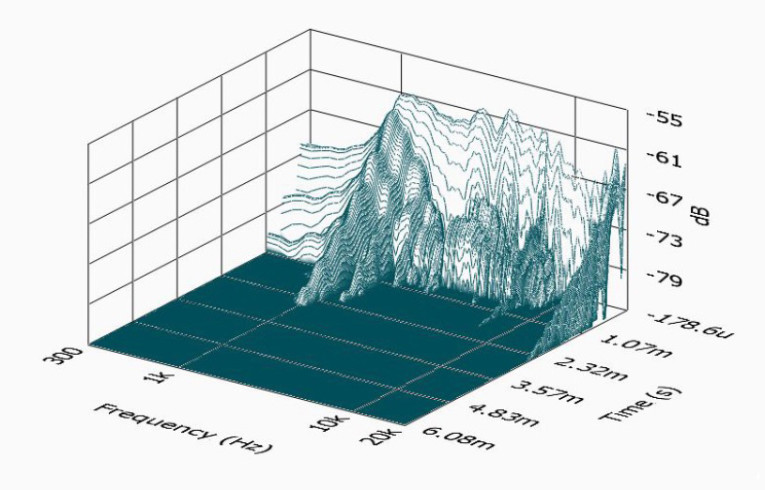
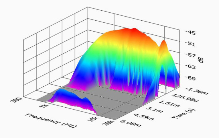
Next, I set up SoundCheck 12 to generate a 2.83 V/1 m impulse response curve and imported the data into Listen’s SoundMap Time/Frequency software. The resulting cumulative spectral decay (CSD) waterfall plot is shown in Figure 9. The short-time Fourier transform (STFT) plot is shown in Figure 10.
B&C Speakers is a consistent manufacturer, with excellent build quality and performance.
www.bcspeakers.com
