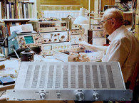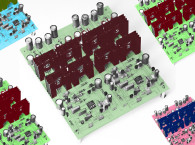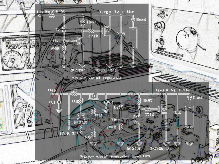
This regulator greatly improves musical handling. The music gets a new dimension: time, timing, and space! And I don’t know of another regulator that has such explosive and live musical performance! Sound image is deep and broad, and it also has details from low down to high frequencies! This low-noise PSU/shunt is meant to power all high end units: preamp, DAC, phono, and so on. Both my DAC and phono were battery powered before, but no more.
Shunt or Series Regulator?
At the outset, I must admit that I am not an electronic engineer, just a passionate 50-year-old hi-fi amateur, with many years of practice and experience! Many of my projects have succeeded, and some of them have not! Some time ago I became preoccupied with the idea of finding a good audio voltage regulator for my preamp. I had been searching the net, and so I encountered encountered many super low-noise, high-speed series regulators. Unfortunately, none of them described how they sounded.
I hoped for a glimpse of the famous STAX shunts, but I gave up. I found some other shunts, but they were not symmetrical designs or did not have the voltages or current I needed. So I bought one of the series regulators — the JSR 03/05, which is super low noise, super fast. The funny thing about this discrete design is that it is supposed to have preregs with LM 337/317, but I left them out, because these preregs sort of compressed the music in one of my older Sulzer designs. This super design could do no better than Erno’s all-FET series reg, and I had to admit that the JSR 03/05 was a waste of money.
I made a simple zener shunt from some old zeners I had, and it was not bad at all. While it was noisy, there was something different about the musical presentation, which I thought was positive. Erno sent me the diagram of an updated shunt model. And from here, one thing led to another, because of the great improvements in the sound. Several listening tests led us to a final shunt version, designed by Erno himself. This final shunt outclassed all the other tested shunts, and is now incorporated in Erno’s unique all-FET series, known by many audiophiles (available online here).
Besides its excellent audio performance, the shunt is capable of absorbing transients in the mains power, coming from refrigerators, oven thermoswitches, and lighting armatures. And also because it delivers a constant-current with constant voltage, there will be no pumping or oscillation of the transformer and capacitors voltage.
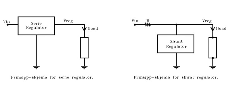
Shunts also have an ultralinear low impedance all over the frequency band and into MHz. It is also called a parallel regulator because it sits parallel to the power supply. In this manner the audio is connected directly to the power supply and does not affect the audio idle or amplifier feedback, but with a series regulator it will. I think this is the main reason for the shunts giving the better musical performance (Fig. 1).
The shunt idea is also based upon shunting current greater than consumed. In my case, I shunted about 400mA for my preamp using 200mA. This amount is overkill, but I had to start somewhere, and mostly all the tests were shunted at about 400, just to eliminate at least one parameter. For later tests I shunted about 330mA, and I don’t think I noticed a degradation of the sound. Greater shunt current gives lower impedance.
The drawbacks are that the shunts consume more power and, much like a Class-A amplifier, became hot, because all the power that is not consumed by the amplifier will end up in the shunt output transistors. Another factor is that the supply and shunt will be bigger than the traditional PS/regulator combination.
Shunt Types
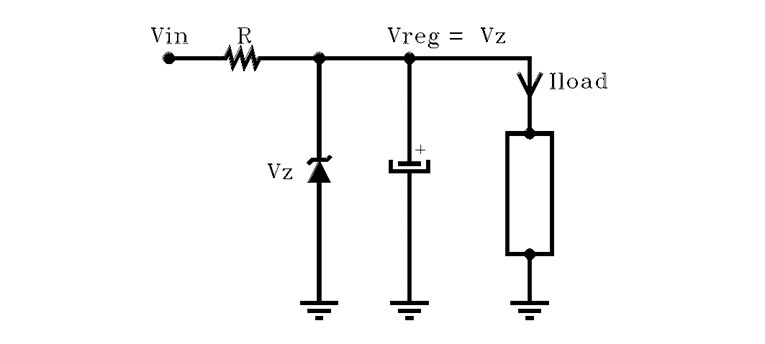
The zener shunt, the simplest of all shunts, consists of feed resistor R, the zener diode, and a capacitor. Resistor R determines the total current that should be sinked by the zener and the load! It is a bit noisy, but I have replaced 3-pin LM regulators with this in buffers with a gain of 2 with good results! This is also the first one I tried on my preamplifier (Fig. 2).
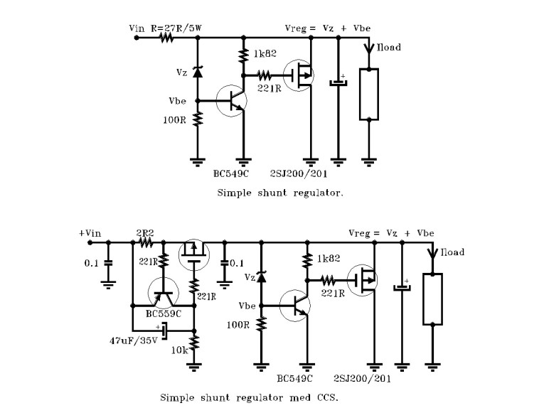
The simple shunt regulator shown in Fig. 3 (top) consists of two transistors, and because of the gain factor, it actively decreases ripple and also noise. You will notice at once the much lower noise of this regulator. Zener diode Vz = 22 gives about 23-24V, and ideal PSU voltage should be 6-7V above shunt voltage (regulated voltage).
If you look at Fig. 3 (bottom), you will notice that the feed resistor 27R is replaced by Erno’s constant-current regulator using a MOSFET. The input resistor of 2R2 gives a current of approximately 300mA. This constant-current fed shunt gives an incredible improvement in sound and sound stage. More about this later. With the all-FET super shunt (Fig. 4) you will notice the same constant-current regulator as in the simple super shunt.
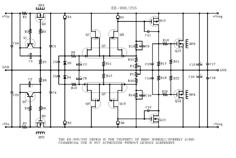
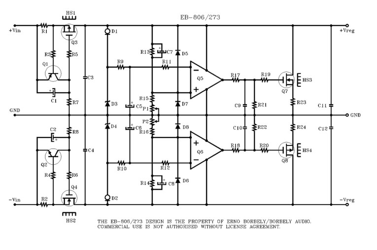
The regulator, which is designed by Erno, uses the sophisticated all-FET topology! The even greater gains in this design offer better regulation and, of course, lower noise. I am now using this with my phono preamp (gain 70dB). Even greater gain is offered by the op amp shunt, and this should theoretically be the best of all the regulators, with lowest noise of them all! You will once again see the same constant-current regulator as in the simple shunt and the all-FET shunt (AFS). Despite the lowest noise of all, it cannot cope with the all-FET super shunt’s musical performance (Fig. 5).
Listening Tests
I have been using battery power for both DAC and MC phono for quite some time. For my preamp I have been using Erno’s all-FET series regulator. And I have already tried out a zener shunt for my preamp, despite the higher noise level. I told Erno I liked the distinct spacious and dynamic sound.
A more important impression was that the loudspeakers became sort of invisible. After I received a diagram from Erno on the simple shunt, it took me just a few hours to hardwire this. With the simple shunt, I could hear the lower noise as well as greater image and sound stage. Dynamics are even better, and bass is deep and powerful, with good punch low down. Even dynamics and bass are greater than my series regs.
I had been playing my new shunts for a few days before Erno faxed me the constant-current regulator, which replaced the feed resistor 27R. I also hardwired this CCS and a solid heatsink onto an output board, as I did for the shunts. I adjusted the current to be about the same as before. Shortly after I was ready to listen and was very excited.
My new constant-current fed simple shunt had less or very little gain com-pared to just the simple shunt, with feed resistors. Also, noise seemed to be lower, with even greater and deeper sound stage. Dynamics and low down attacks were super, and so was detailing. This shunt gives you a realistic sound stage, like sitting in the third or fourth row of a concert. The dynamics are like having my amplifiers bridged, which they are not. I was so impressed by this regulator I built another very soon afterwards and was so impressed that I threw away my battery supply (eight Panasonic HV12-07 and 40,000μF capacitors, and the charging equipment).
With all respect to the Panasonics, they tended to be flat and dull compared to my new shunts. I even used this with my phono: Erno’s all-FET MC, gain 64dB. Even with lots of noise, I still preferred this to both series regs and batteries. After I conferred with Erno, we agreed to do something about the noise. He wanted me to test two completely new shunt models, one discrete design and one op-amp based. And, of course, they should be constant-current fed. They would be readily assembled, tested, and sent to me.
I had to admit I didn’t believe further improvements to the sound by the new shunts were possible. Still I hoped when the new shunts arrived. I had already made a pair of plug connections to plug in or out of the different shunts!
All-FET Super and Op-Amp Shunts
A brief listening test of both shunts indicated that they both had extremely low noise and produced deep sound stage and super detailing mid and top! But the greatest difference was the much smaller sound stage. The worst was that bass could not cope with mid and high frequencies; and they lacked punch low down, too. I was surprised, and a bit disappointed.
I went through the diagram for the shunts, and I noticed that Erno used other output transistors and a source resistor. With all respect for the 2SK2030/J313, I wanted to replace them and short out the source resistor! I used my own transistors, K 1530/J 201 for CCS and the same or IRFP 150/9140 as shunt elements. It happened to be the only choice of power transistors in all the shunts. But every attempt to alter the components of these low-noise shunts was rewarded with oscillation!
Very frustrated, I gave up on the opamp shunt for the moment and concentrated on the all-FET super shunt. This one at least became stable with a compensation capacitor to the output driver, C11 and C12. I did more tests with other components and had some real bad experiences. It was partly my own fault, because I used a different PSU, transformer, and caps. I had to go back and do the tests again, but this time with the same PSU.
Listening to the upgrade, I noted that the bass, mid and high frequencies all played together now, in a manner similar to the CCS/SS, with a deeper and broader sound stage. It was never grainy, and seemed to have extended low and top. The ideal use was, of course, for my phono, because of the very low noise, but I was also using it for my DAC. I loved the CCS/SS for the very close sound stage, although it was noisier and a little bit grainy on some occasions! It was difficult to decide which of them I preferred, so I used both, switching between them.
Final Upgrade
Trying to make op amp shunt sound better led to the final upgrade of AFS. I tried more op amps, and did the same transistor mod, as with the AFS. With the LF411, it played very convincingly, with all the details but the smallest sound stage. It also had incredible dynamic and punch, even better than the AFS. I wondered about this for a few seconds, then I remembered that I had changed the 47μF ELNA with MV-AX Panasonics, in an earlier attempt to stop oscillation. I wanted to try this cap mod with AFS.
I don’t regret changing these caps, because now this shunt plays like a refined CCS/SS, with extended bottom and top ends. And, of course, the dynamic was increased, and the sound stage is very like CCS/SS. Building a second one later just confirms the improvements with even more open and clean sound stage. I now have four AFS regulators; the latest was to my hybrid tube headphone amp (and AKG 701). Before this it was fed with Panasonic batteries and capacitors.
Impressions by Shunting Power
I have no fancy loudspeaker cable, interconnects, nor perfect speakers, but I have never played such realistic music. I don’t think you will find any cable that will give you the same improvement as this shunt does! I have tried many cables myself, and some are good. But I refuse to accept any cable that costs more than a high-quality industrial cable. Think of what cables record studios are using.
Ups and Downs
Testing the AFS and op amp shunt was frustrating from start to finish, working with both at the same time. I had to put away the op amp shunt for a moment, because all my modifying attempts were rewarded with oscillation or bad sound. The AFS remained stable after just one compensation capacitor, and I modified it more times without trouble. I also tested two transformer sets and two capacitor banks. This expensive transformer and caps reversed the whole progress, and I had only myself to blame. The moral of the story is to use exactly the same transformer set and capacitors I used for the successful CCS/simple shunt. I had to do all the listening tests again.

Selecting Components
A very good help when selecting components has been Erno’s ladder attenuator, with Caddock and Dale resistors. This attenuator has an incredible open and transparent sound. The genius of it is that the signal goes through only two resistors, regardless of attenuator position! At the same time, in balanced applications, it will be 100% balanced in all positions, just as the feed resistors are equal. See Fig. 6 ladder attenuator.
Power Supply Demands
To get the best out of the shunt, you must have a rigid, stable power supply! That means bigger transformers and greater capacitors than used with the series regulators. I have also tested some transformers. My first choice is the R-core transformer, which has incredibly clean sound and transparent sound stage. The mechanical noise here was the lowest of all. They smelled good, too. I tested the 120 VA, and used two of them!
My second choice was the Plitron toroids from Canada. I tried two of the 160 VA, which produced a very clean sound, with a little warmer presentation in the mids and lows. Also these had very low mechanical noise.
My third choice, and the best above 100 VA, was the fully encapsulated transductor, formerly Noratel. These sounded best of the big toroids, and had low mechanical noise. Some of the other big — not encapsulated, or center encapsulated — units had punch and bass, but tended to add a gray mist to the sound, not so fully transparent as the best. The small toroids — 30 to 50
VA — seemed to compress the music and lacked attack and bass. These were also very noisy, despite a maximum rating of 1A and consuming not more than 0.2-0.3A! I also selected the capacitor and rectifiers from listening tests when I earlier tested series regulators.
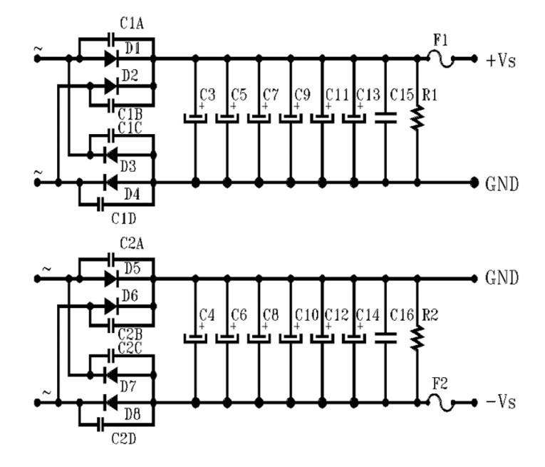
For signal audio amps and power amp driver boards, I always use dual secondaries and two bridge rectifiers (Fig. 7). For the rectifiers I have used both BYW28, 4A, and HFA08, 8A. The only capacitor is Panasonic FC, which has low ESR and low impedance. But you must have many of them paralleled. I suggest minimum 20,000μF per rail for shunting 200mA, and 30,000μF for 300mA. Use as many as you can afford, which gives a more distinct and rock steady listening image.
The Panasonics have simply no comparison, with their ultra smooth frequency band and no coloring. You could, in fact, mix in some Sanyo MV–AX components, but not too many, because they tend to sound a bit clinical. I have a drawer full of new Nichicon, ELNA Cerafine, ALS 30, PEH 169 /200 capacitors, and they all sounded bad. And just paralleling the Panasonics with the other caps degraded the sound.
At Last
I wish to thank Erno Borbely for his contribution to this project, and his assistance in working out problems. If you are planning to build any amplifier, I cannot think of any better choice than his new-generation all-FET audio series. aX
References:
For more on Erno Borberly and his all-FET designs read these articles:
http://www.audioxpress.com/tags/Erno-Borbely
Tips When Building
Always test the shunts one after another for oscillation, with load. I like to be sure of a stable condition and tested with no load condition, but only for a short moment. And be sure to test with the shunts built into the cabinet. I recall one occasion in which there was no oscillation outside the cabinet, but there was inside when hooked up to the amplifier! I solved this by insulating input/output grounds, and grounded only outputs to the chassis via 0.1μF!
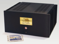
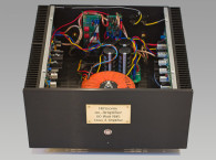
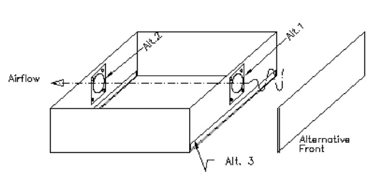
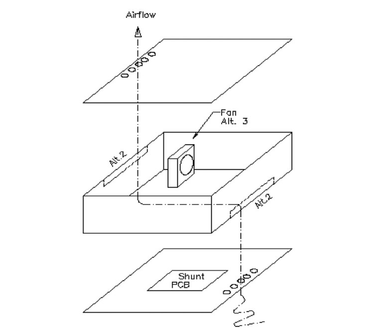
Another consideration is that the shunt PSU and regulator use more space because of bigger transformers and capacitors and larger PCBs and heatsinks. You also must transfer the heat away. You might consider building a separate cabinet for the shunt supply, including transformers. The ideal enclosure is vented top and bottom. If you want to use a closed box, you must make some slots or holes in the top, bottom, front, or back plates. My enclosures are shown in Figs. 8 and 9.
You could also install a little fan (6 × 6 cm) for better cooling. I used an old cell phone charger 5-6V DC to feed a little 12V fan, which is practically noiseless. It is also a good idea to mount the capacitors in the coolest place in the cabinet. For phono use you should have the transformers in a separate enclosure, at least 1m away. And use thick cables 0.75-1.0mm2 for the supply, preamp, or DAC. For long supply cables, I have mounted a pair of Panasonic 2200μF or 3300μF capacitors in the preamp or DAC cabinet close to the amplifier
V+/V-.
For power plugs I use the cheap DIN U 8 or DIN C 8, and all my power connects have the same pinout pinout and are compatible. I have used these for more than ten years, and despite heavy use, they have never failed. — AW
This article was originally published in audioXpress, February 2008


