Wood-cased radios have especially good sound quality, and the battery compartments in antique “portable” radios (like the Philco 48-360 or the Zenith Transoceanics) provide perfect locations for additional circuitry. When restored properly, large furniture-style radios that were built for “high fidelity” (like the late 1930s and early 1940s Philco console radios) can fill a room with rich beautiful sound.
The three most significant recommendations I can make concerning restoring old mains-referenced electronics are: be sure to install a polarized power cord; add a fuse at the hot mains power entry; and if necessary, re-wire the external power entry so that the on/off knob switches the hot mains wire so that the internal chassis is neutral-referenced.
Accessible Restoration Resources
Many organizations and websites are dedicated to the restoration and collection of antique tube radios. Definitely check out www.antiqueradio.com, www.antique-radios.org, www.dxzone.com/catalog/Antique_Radios/Clubs, and www.antiqueradio.it. Searching the web for subjects like “replacing capacitors in old radios” yields interesting advice. Ad-ditionally, there are many excellent books describing radio restoration, the “Books, etc. for sale” link at the website www.antiqueradio.com is an excellent place to start.
Because of this available supply of restoration information, this article will focus on circuit modifications designed to repurpose these antique radios into amplifiers, without altering their appearance or original radio functionality.
Simple Circuits
The simple circuits described in this article perform two functions. They mix an external line-level stereo signal (typically from an MP3 player or computer) and reference it to the radio’s circuit. They also use the radio’s on/off knob to switch this external signal to the radio’s audio amplifier.
There is not one circuit that will work for every antique radio. (Original schematics for antique tube radios are available on the web www.justradios.com). But the circuits described here can be adapted to any radio topology. All the parts can be ordered from an electronics supplier like Digi-Key, and the circuit can be soldered on a prototyping printed circuit board (such as RadioShack P/N 276-168B).
External audio mixing
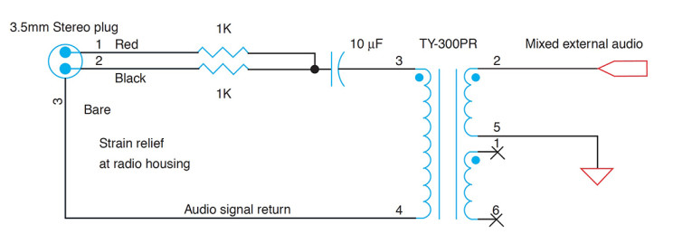
Figure 1 and Figure 2 show some examples of circuit schematics that mix the line-level stereo audio signals together (almost all tube radios are monophonic), while providing galvanic isolation from high voltages within the radio. Figure 1 shows an inexpensive solution suitable for most table-top radios. These radios have relatively small speakers that are unable to reproduce deep bass, so an inexpensive audio transformer (available from online distributors) does the job. I picked up a bucket of Tamura TY-300PR transformers for $0.50 each at an electronics surplus store, and similar transformers are commercially available.
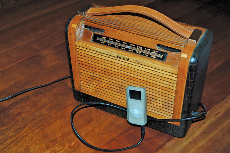
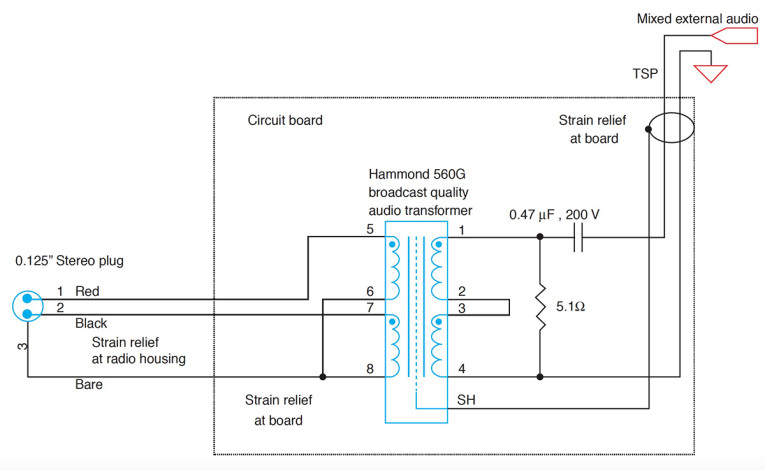
Alternatively, the Hammond 560G shown in Figure 2 is an expensive, high-quality audio transformer suitable to high-fidelity radios (like the furniture- sized Philco consoles). A less expensive (and fine-sounding) alternative is the Hammond 148A. I use Belden 9154 twisted, shielded audio cable for wiring internal to the radio, but twisted, 24-gauge wire will work well. An 8' long audio cable with a 3.5-mm stereo jack on each end can be cut in half to make input cables for two radios, or you can use the cord from trashed ear-buds. You can route the audio cable out the back of the chassis. Photo 1 is a photograph of a 1948 Philco portable tube radio restored and used as an digital player amplifier.
Audio switching using the radio’s on/off knob
After creating the mixed, radio-referenced signal, the next step is to build a circuit that switches the voltage driving the radio’s audio amplifier between its own internal broadcast and the external audio signal. Figure 3 illustrates this audio routing control using the radio’s existing front panel power knob. Turn the radio on, and it behaves like the old analog radio it was designed to be (after the tubes warm up). However, if you turn the radio off, then on again within a few of seconds, the external audio signal is routed to the radio’s tube amplifier and speaker.
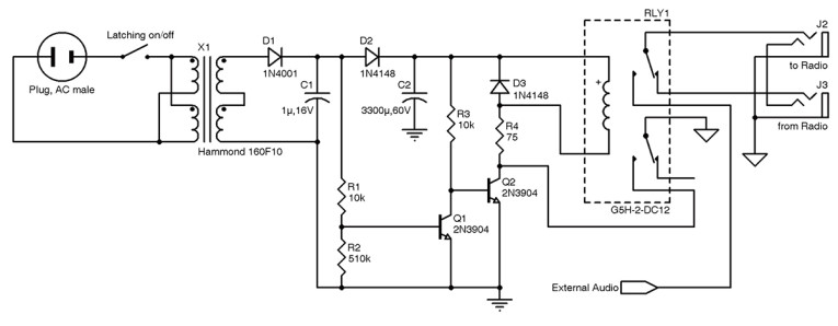
The circuit shown in Figure 3 uses a transformer to create the low voltage used by the switching circuit. There are many alternative power transformers available, and many methods of creating a transformerless power supply. Use your favorite. In Figure 3, the connector in that is labeled “From radio” represents the audio signal coming from the radio’s AM detector circuit, and the connector labeled “To radio” is the selected audio (either the radio station broadcast, or the MP3 player signal) that we are sending back to the radio’s audio amplifier. Figure 4 shows how these signals interface to the radio circuit.
When the radio is initially powered on, the lower 2N3904 transistor turns on. This pulls down the base of the higher transistor, turning it off and keeping the relay coil de-energized. In this state, the radio audio is routed through the relay to the radio’s audio circuit. When the radio power is switched off, the lower transistor switches off and allows the upper transistor (powered for a few seconds by the large capacitor) to turn the relay on. The relay latches itself on through its lower contact. In this configuration, the relay routes the external audio signal to the radio’s volume control, and from there it feeds the radio’s output amplifier. If the radio is switched back on within a few seconds, this state is maintained, and the radio serves as a tube amplifier with its volume still controlled by the radio’s volume knob. When the radio is eventually turned off, the circuit discharges and returns to its original radio configuration.
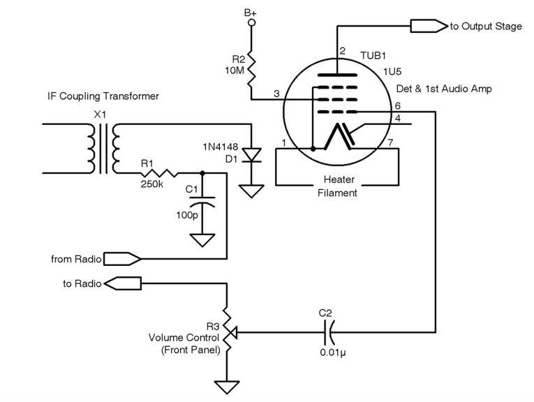
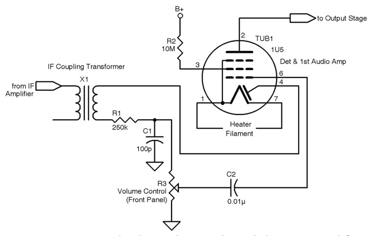
Now that we can switch the signal to the tube amplifier, we need to modify the radio’s circuit to accommodate our external audio signal. We will examine a representative radio circuit. The volume control knob is usually the best place to switch in our audio signal. Figure 5 shows a typical circuit adjacent to the volume control potentiometer in an antique radio. The IF (intermediate frequency) signal (which has been mixed down from the received RF signal) is rectified by the diode of the 1U5 tube (1U5, pin 4) and low-pass filtered (to remove the IF frequency content) before being presented to the volume control knob as an audio signal.
We hijack the signal between the low pass filter and the volume potentiometer (see Figure 5) and route it to our switching circuit. Also, to reduce the radio signal bleed thorough into the first audio amplifier (because the IF signal’s rectifying diode and the audio amplifier pentode are in the same tube), we can replace the vacuum tube diode with a semiconductor diode.
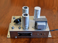
The next photos (see Photo 2a and Photo 2b) show our additional circuit mounted in the lower (battery) compartment of a Zenith Transoceanic AM/shortwave receiver.


Note the new high-voltage (B+) capacitors (part of the radio’s restoration) attached to a transformer housing with blue tie wraps. The added circuit board that performs the audio re-routing is mounting to a 0.125" maple plywood base, using screws countersunk from underneath. The plywood is securely screwed to the inside base of the radio housing.
Rubber grommets are added wherever cables pass through the radio’s steel frame. Careful, patient workmanship is the key to a safe and successful radio restoration, and the reward for adding the capability to play external audio is a classic amplifier with vintage tube sound. aX
Warning: Antique tube radios contain dangerously high, mains-referenced voltages. Always use an isolation transformer when powering a radio in the shop. Never work on a radio when it is powered, and discharge high-voltage capacitors to avoid electrical shock. Do not attempt any repair or modification of mains-powered electronics unless you understand electrical safety.
This article was originally published in audioXpress, May 2012.