The signal-to-noise ratio (SNR) and dynamic range of conventional capacitive microelectromechanical systems (MEMS) microphones have been improving incrementally over the last 20 years and are now approaching the limits of the technology. State-of-the art digital microphones are reaching an SNR of 73dBA and a dynamic range of 101dB, demonstrating the significant challenges of simultaneously achieving a low noise floor and a high clipping point in a digital microphone. Piezoelectric MEMS microphone technology promised to surpass the performance of capacitive microphones, but to date has only delivered an SNR of 64dBA with a dynamic range of 90dB.
Until now the only solution available for audio capture in premium systems requiring exceptional electroacoustic performance has been the legacy electret condenser microphone (ECM), which is limited by the challenges of analog interface, large size, inferior part-to-part matching, poor stability, and the need for manual soldering.
The SBM100 series optical MEMS microphone has smashed the limits of SNR and dynamic range of miniature microphones. With 80dBA SNR (14dBA noise floor), 132dB dynamic range, 24-bit digital output and with low power consumption, the microphone is the long-awaited solution to electroacoustic challenges in high-performance audio and sound acquisition applications. These applications include enterprise video conferencing systems, 3D spatial audio capture, active noise cancellation (ANC) headphones, high-end smartphones, and many more.
So, how has sensiBel, a dynamic Norwegian high-tech company, achieved this significant breakthrough in MEMS microphone electroacoustic performance? Using MEMS technology, advanced complementary metal-oxide-semiconductor (CMOS) circuit design, a laser optical subsystem and miniaturization in electro-optical packaging, sensiBel has created the SBM100 product series of optical MEMS microphones that address the challenges in the market. This first-generation optical MEMS microphone breaks the performance barriers of conventional microphones and enables true studio-quality performance in a small package.
Optical MEMS Microphones
The SBM100 optical microphone is comprised of a laser optical subsystem and a digital ASIC for signal processing, packaged as a micro-assembly in a small 4.8mm×3.8mm×2.8mm top port surface mount package. The laser optical subsystem is comprised of a VCSEL, a photodetector, and a MEMS device including a diffractive optical element (DOE).
This technology is a breakthrough in microphone performance that brings great flexibility to audio system designers of modern acoustics systems in a wide range of applications. A digital microphone with an 80dBA SNR, wide dynamic range and low part-to-part variation significantly simplifies the design and cost of downstream signal processing for audio and sound acquisition, especially for multi-microphone beamforming applications. Table 1 summarizes the SBM100’s key product features.
The SBM100 microphone has a flat frequency response up to 20kHz and a low frequency -3dB point at 10Hz. This means that the microphone has excellent phase matching at low frequencies, making it ideal for modern active noise cancelling applications that require excellent phase response and very low noise. The output is highly linear up to the acoustic overload point (AOP) of 146dB SPL. See the frequency response and linearity shown in Figure 1.
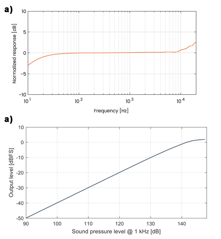
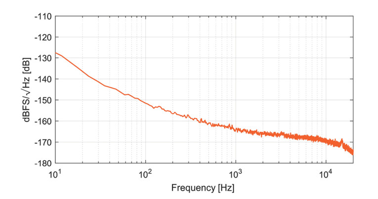
The microphone has a very low self-noise with an equivalent input noise (EIN) of 14dBA SPL. This equates to an SNR of 80dBA. See the SBM100’s input noise spectral density plot shown in Figure 2.
Miniature Microphone Technology Advancement
The ECM invented in the early 1960s represented a breakthrough in the ability of acoustic systems to acquire audio input information. The ECM enabled modern consumer devices to record audio cost effectively with a built-in microphone that was not prone to system vibration.
ECM microphones, however, are not reflow solder compatible and do not have good part-to-part sensitivity matching. With the explosion of consumer devices such as mobile phones and PCs in the 1990s, there was a need for a microphone that could be supported on high-volume surface mount technology manufacturing flows.
In the early 2000s, MEMS microphones were introduced that could withstand reflow solder temperatures and had good part-to-part sensitivity matching. MEMS microphones were available in both analog and digital output format.
Initially, digital MEMS microphones had an SNR in the low 60dBA range. Developments in both MEMS and ASIC technology have driven improvements in SNR and the current best-in-class digital MEMS microphone has an SNR of 73dBA. To achieve this level of performance, the MEMS capacitive element has evolved significantly, and the state-of-the-art microphone is comprised of dual membranes with a single backplate combined in a localized vacuum. It is increasingly difficult to further reduce the noise floor of the MEMS element and ASIC as we approach the fundamental capability of capacitive MEMS microphone technology.
In parallel with the advancement of SNR in digital MEMS microphones, many applications demand the capability to perform at very high sound pressure levels (SPLs), for example, in loud environments or when the microphone is mounted close to a loudspeaker. The dynamic range of a microphone represents the range between the noise floor and the point where the output of the microphone is highly distorted, defined as the AOP where the total harmonic distortion (THD) is at 10%. Over the last 10 years, little progress has been made on advancing the dynamic range of digital MEMS microphones primarily due to inherent trade-offs between optimized noise floor and clipping point of the microphone. Specifically, the capacitance-to-voltage readout technology puts a heavy burden on the design of the analog-to-digital converter (ADC) and often requires a dual front-end solution to cover the entire voltage range of the output.
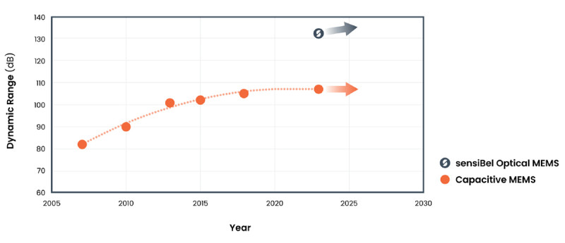
Figure 3 shows how dynamic range has improved slowly in digital microphones over the last two decades and how the SBM100 represents a significant breakthrough in performance.
The capacitive MEMS element sensitivity is a key contributor to the microphone noise floor. However, high MEMS sensitivity will generate high voltage output levels at higher SPLs and every 6dB increase of sound pressure will yield a further doubling of this voltage. So, at some point the ADC will be unable to manage these high voltage levels at the input. Similarly, a doubling of SPL will result in a doubling of the displacement of the diaphragm. With the gap between diaphragm and backplate of a capacitive MEMS microphone in the order of a few microns, the diaphragm and backplate will come into contact at high sound levels. The high voltage levels and mechanical constraints lead to a trade-off between SNR and AOP.
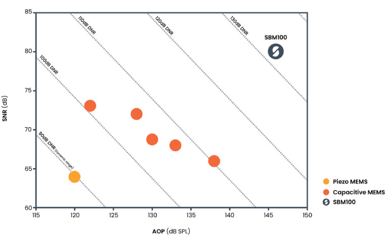
Figure 4 shows the progress in driving dynamic range by plotting SNR against AOP for various digital microphones. The plot represents the best-in-class digital microphones on the market today. The sensiBel SBM100 clearly represents a major leap forward in dynamic range by pushing the limits of SNR and AOP simultaneously.
History of Optical MEMS Microphone Technology
Work on optical MEMS microphones has been ongoing for more than 20 years as shown in Figure 5. In 2003, Sagberg, et al. [1] described work at SINTEF, a Norwegian independent research organization, presenting research on an optical microphone based on a modulated diffractive lens. In 2004 Lee, et al. [2] presented progress on an optoelectronics-based micro-machined acoustic sensor summarizing that the technology should be able to achieve a noise floor in the range of 20dBA (74dBA SNR).
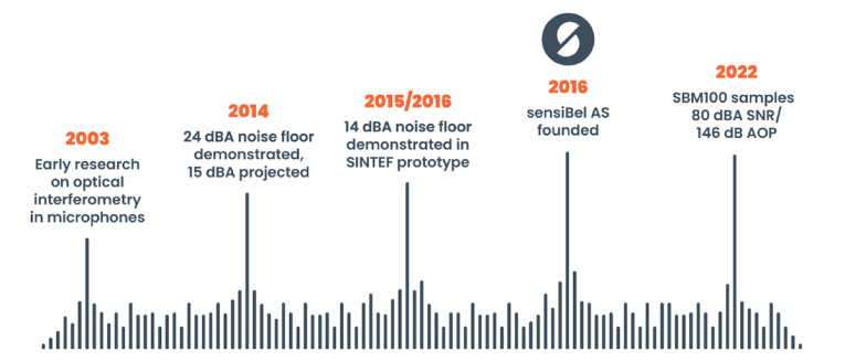
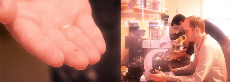
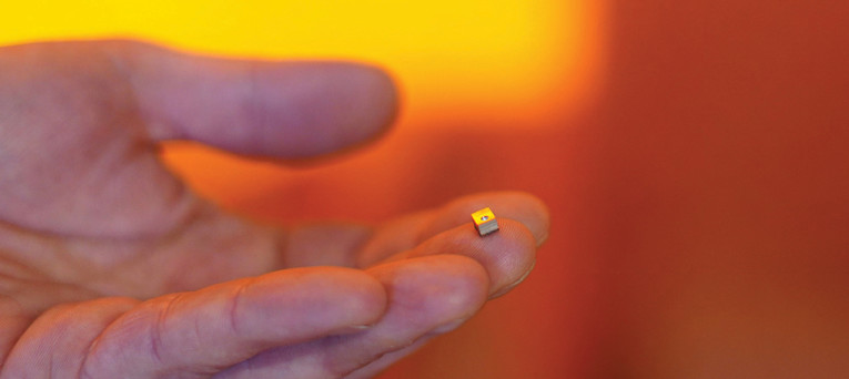
By 2010 various research labs reported results on proof-of concept designs to demonstrate viability of the technology. In 2014, Kim et al. [3] presented an optical micro-machined microphone that achieved 24dBA self-noise and predicted that the technology can achieve a noise floor of 15dBA. Around this time, researchers at SINTEF demonstrated a proof-of-concept prototype optical MEMS microphone solution with 14dBA noise floor (80dBA SNR), and based on this work, sensiBel was founded in 2016 to commercialize the technology. sensiBel has since significantly optimized and miniaturized the prototype and transferred production to high-volume capable fabrications. In 2022, sensiBel started delivering miniaturized SBM100 samples to customers. Photo 1 shows the fully packaged SBM100 optical MEMS microphone including an ASIC with digital output.
Microphone Construction
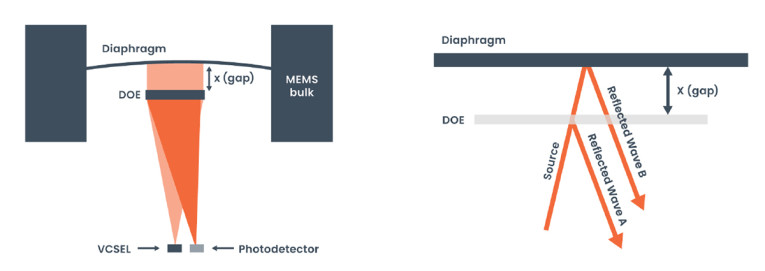
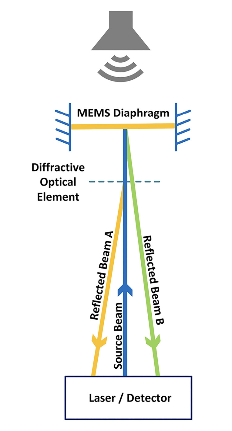
The MEMS structure is a simply supported diaphragm with a reflective coating and a Diffractive Optical Element (DOE). Figure 6 shows the basic construction and operating principle of the optical microphone system. There is no conventional backplate in the optical microphone construction and the DOE is spaced tens of microns from the diaphragm. The VCSEL produces a coherent optical beam that impinges on the DOE. A portion of light is reflected at the DOE and the remainder of the beam passes through the DOE and reflects off the bottom surface of the diaphragm. Consequently, two independent beams, A and B, are formed. The signal at the photodetector represents the optical interference of these two beams. The fundamental principle of operation is interferometric phase modulation. sensiBel has developed a photodetector-based optical signal detection system that acquires this phase-modulated interference pattern and converts it into an output that represents the displacement of the diaphragm.
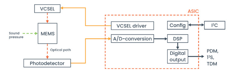
This optical subsystem has been miniaturized and packaged with an advanced mixed-signal ASIC that manages the complex processing of the photodetector output. Figure 7 shows the overall system’s block diagram.
The SBM100 series supports standard pulse density modulation (PDM), I2S and eight-channel time division multiplexed (TDM) output formats with 24-bit resolution. An I2C interface can optionally be used for configuration of advanced microphone features. The system is packaged in a standard top port surface mount package that can be reflow soldered into the end application.
Interferometer Principles in Optical MEMS Microphones
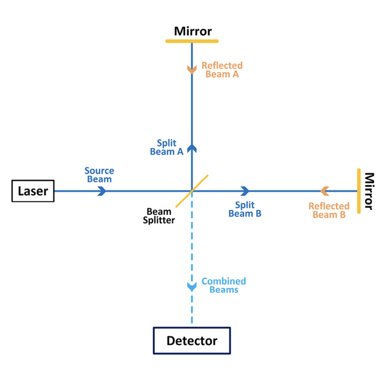
The fundamental building block of the patented sensiBel optical MEMS microphone is the interferometer. An interferometer is basically comprised of a single coherent laser light source that is split into two different paths and then recombined, and interference of the combined light can be interpreted as a difference in path length between the two resulting beams. The interferometer is used in many diverse applications to make dimensional measurements at femtometer precision.
Figure 8 shows the basic construction of a classic Michelson Interferometer. Beam A and beam B are split from a single source. When they recombine, the phase difference between the beams defines the intensity pattern that will be seen at the detector. If the path length of beam A and beam B are the same, there will be no phase difference and thus constructive interference. If the path length differs by a half wavelength, destructive interference will result. Any intermediate phase difference will result in an intensity pattern that is a function of the phase difference.
The sensiBel optical microphone works on this same fundamental principle of interferometric phase modulation. A DOE is placed between the laser source and a reflective MEMS diaphragm. A proportion of the laser source is reflected by the DOE and the remaining light continues and is reflected at the MEMS diaphragm surface and returns to the detector. The phase difference between the two beams is a function of the distance between the DOE and the diaphragm. Figure 9 shows a simplified representation of the construction of the optical microphone. A variation of SPL will cause diaphragm movement, which results in a path length difference between beam A and beam B. The light intensity pattern is detected by photodetectors and is interpreted to determine the diaphragm’s position.
The light intensity at the photodetectors will change depending on whether the two light beams create constructive or destructive interference. The DOE will direct light into different directions depending on the relative phase between wave A and B, thus creating a phase-modulated interference pattern in the photo-detector plane. The light patterns at the photodetectors are interpreted by a DSP in the ASIC (Figure 7) to generate the audio output of the microphone.
The photodetector current is represented by the common equation for two-beam interference from optics and wave theory:
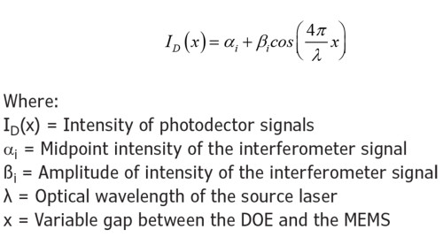
The intensity of signal at the photodetector is a cosine function of the gap x between the MEMS diaphragm reflective surface and the diffractive optical element. The plot in Figure 10 shows how the output current will vary when the MEMS gap changes by one half wavelength.
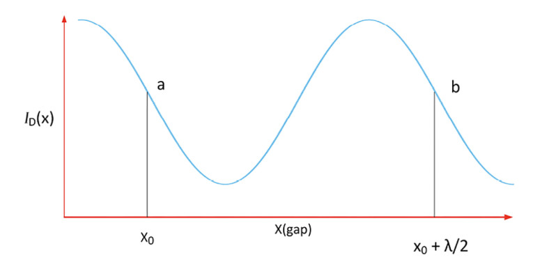
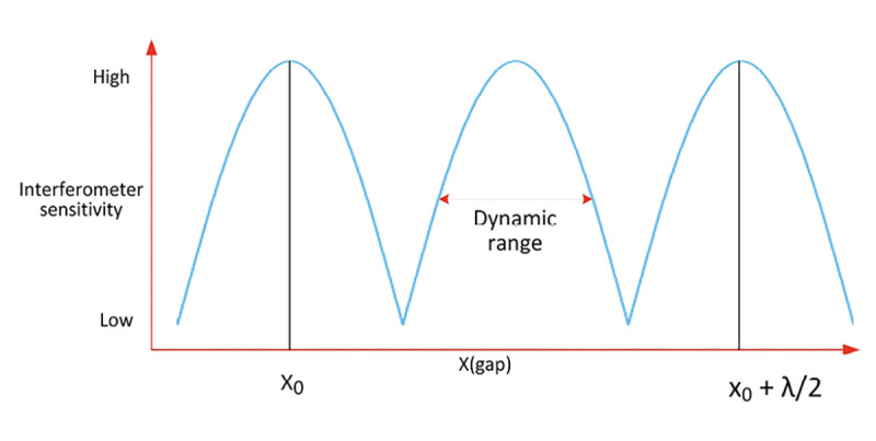
The microphone output sensitivity is a function of the rate of change of the photodetector signal intensity. From the minimum point on the cosine wave to the maximum point the rate of change or output sensitivity is maximized. At the turning points the sensitivity is effectively zero.
Figure 11 represents the absolute value of the derivative of the cosine wave. Using this basic system construction, the dynamic range of the microphone is defined by the output with contiguous useful system sensitivity as shown. The digital processing of the photodetector output converts this output signal into a linear acoustic signal. Building on these fundamental concepts, sensiBel has created a sophisticated proprietary optical subsystem coupled with a digital ASIC in a miniaturized package that delivers 80dBA SNR with 132dB dynamic range.
Advantages of the SBM100’s Mechanical Construction
There are several aspects of the novel SBM100 optical MEMS microphone’s construction that are very advantageous to microphone performance:
- There is no noise contribution from air movement through small backplate holes
- The gap between the diaphragm and the DOE is in the order of tens of microns, an order of magnitude larger than capacitive microphones.
Consequently:
- There is no significant squeeze film damping in the system. Squeeze film resistance between two surfaces is a significant source of noise and is proportional to 1/x3 where x represents the gap between the two surfaces.
- The diaphragm can move tens of microns, so there is no practical mechanical limit to the AOP.
- There is no risk of mechanical stiction between the diaphragm and a backplate due to material adhesion or the presence of contamination. Stiction (static friction) is a well-known failure mechanism in MEMS devices, where two surfaces come into contact and adhere.
- As the MEMS element is electrically passive, there is no voltage bias on the MEMS. In capacitive MEMS devices the diaphragm and backplate can adhere when the electrostatic attraction forces between the diaphragm and backplate exceed the restoring forces of the system. This is not a concern in the SBM100.
In contrast, the listed characteristics limit performance of a capacitive MEMS microphone. The main noise contributors for a capacitive microphone are the small gap between the diaphragm and backplate and the resistance of thousands of small holes in the backplate.
These noise contributors are shown in a basic lumped element model (Suvanto [4]) in Figure 12a and include back volume, backplate perforations, membrane to backplate gap, package vent and the membrane compliance. The basic construction of a capacitive MEMS microphone is shown in Figure 12b.
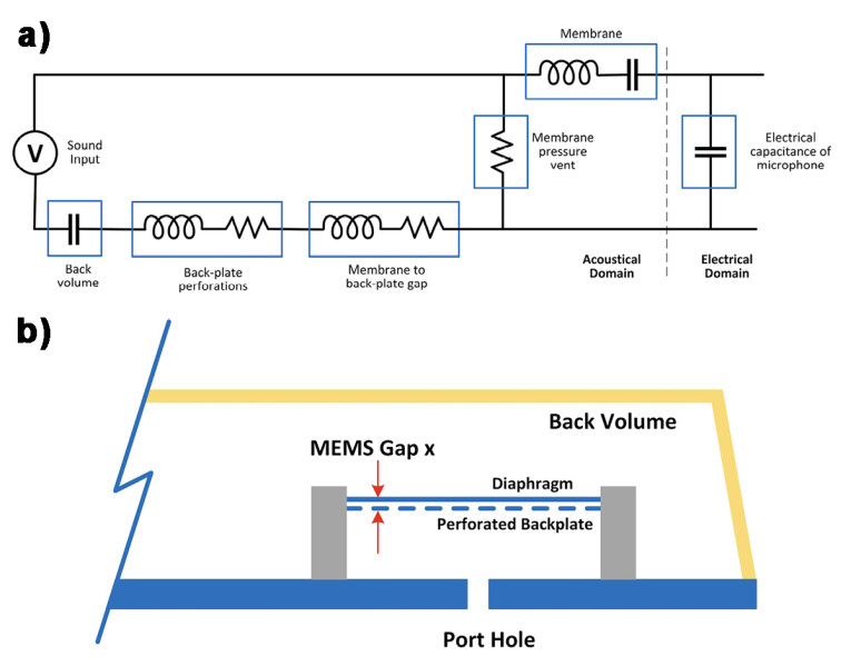
Squeeze film damping is a significant contributor of noise in a capacitive MEMS microphone because the gap between the diaphragm and perforated backplate is in the order of microns. Squeeze film resistance between two surfaces is a function of 1/x3 where x represents the gap between the two surfaces. In a capacitive MEMS microphone the gap is in the order of a couple of microphones while the sensiBel microphone gap is an order of magnitude larger, reducing the backplate gap resistance significantly.
The movement of air through the perforated backplate is also a significant source of noise in capacitive MEMS microphones. In a capacitive MEMS microphone design, the backplate is perforated with thousands of small holes to reduce damping resistance between diaphragm and backplate. The total capacitance between backplate and diaphragm is a function of the plate area, so the density of hole perforation will affect the capacitance. Consequently, there is a trade-off between maximizing the backplate hole and maximizing the system capacitance. Air movement through these holes is also a source of noise. Some new technologies apply a low-pressure/vacuum-sealed structure that reduces the damping resistance. However, such technologies have other design constraints, such as mechanical collapse due to the vacuum, and still suffer from the fundamental challenges in the ASIC-MEMS capacitive interface.
The AOP of a capacitive MEMS microphone is constrained by the small gap between diaphragm and backplate and the very large voltage output generated by high acoustic signals at the input.
The mechanical spacing between the diaphragm and backplate constrains the compliance of the diaphragm. If the compliance is too stiff the sensitivity and noise performance of the microphone will be compromised. If it is too compliant, the diaphragm will strike the backplate at relatively low SPLs. So, there is a trade-off between system SNR and AOP in a capacitive MEMS microphone which restricts the dynamic range, typically in the order of 100dB to 110dB as shown in Figure 4.
The bias voltage of a capacitive MEMS microphone is a factor in the sensitivity of the system. The bias voltage is limited by the phenomenon of “electrostatic capture.” If the electrostatic attraction between the diaphragm and the backplate is larger than the mechanical restoring forces of the system, the diaphragm will stick to the backplate. The lower the bias voltage, the lower the system sensitivity and so the effective dynamic range of the system is constrained. In the case of the sensiBel optical microphone, the sensing element is electrically passive.
Very high signal levels create challenges for the ADC of a capacitive microphone. A very high SPL event will result in a very high voltage output from the MEMS capacitor. This can result in saturation of the ASIC analog front end, which typically is limited by the ASIC, defined by power supplies in the range of 1.2V to 3.6V depending on the application.
This results in the need for sophisticated design solutions to manage these high voltages. The capacitive MEMS diaphragm and backplate can also adhere together due to high voltage bias levels or contamination between the diaphragm and backplate.
The sensiBel optical system design is not constrained by these factors because of the design of the diffractive optical element and its distance from the diaphragm.
Optical MEMS Microphones - The Future
The SBM100 product series represents the market entry of optical MEMS microphone technology and provides a generational shift in performance. It offers audio designers opportunities to improve system design and create applications with new performance levels that are otherwise difficult to implement today. Achieving 80dBA SNR (14dBA noise floor) and 146dB SPL AOP represents a dynamic range of 132dB, which is a breakthrough for digital microphones. The various digital interfaces (PDM, I2S and eight-channel TDM) offer flexibility and opportunities for simplification of the full audio signal chain.
But it doesn’t stop there. Work is already under way for the next-generation optical MEMS microphone based on the same fundamental breakthrough technology. The next generation will include further performance enhancements, reduced package size, added digital programmability, bottom port packaging, and more, to drive the optical MEMS microphones technology to very high-volume markets. aX
References
[1] Sagberg, Hakon, et al., “Optical microphone based on a modulated diffractive lens,” IEEE Photonics technology letters, 15.10 (2003), pp.1431-1433.
[2] Wook, Lee, et al., “Fabrication and characterization of micromachined acoustic sensor with integrated optical readout.” IEEE Journal of Selected Topics in Quantum Electronics, 10.3 (2004), pp. 643-651.
[3] Kim, Donghwan, and Neal A. Hall. “Towards a sub 15-dBA optical micromachined microphone,” The Journal of the Acoustical Society of America, 135.5 (2014),
pp. 2664-2673
[4] M. Suvanto, The MEMS Microphone Book, Mosomic, 2021.
This article was originally published in audioXpress, November 2023
About the Authors
 Jakob Vennerød is the co-founder and Head of Product Development at the Norwegian MEMS startup, sensiBel. Previously he worked on several research projects in audio and acoustics at SINTEF. He has extensive experience in acoustics, electronics, and signal processing, particularly in audio technology. He has a master’s degree in Electronic Engineering and Acoustics at the Norwegian University of Science and Technology, and has co-authored several patents related to microphone technology.
 Kieran Harney is responsible for business development in the Americas for sensiBel. He has been in the MEMS industry for 28 years and he recently served as Managing Director of Audio Products at TDK where he played a leadership role in product development, marketing, and business development of MEMS microphones. Earlier in his career, he started a successful MEMS microphone business at Analog Devices (ADI) in 2005, that was later sold to InvenSense in 2013 and is now part of TDK