MEMS microspeakers are driving one of the fastest technological transitions in the miniature speaker market. MEMS transducers first gained widespread attention in the late 2000s with the first commercially available MEMS microphone, and over the course of a decade, they replaced electret microphones in the majority of mobile devices. The MEMS speaker revolution is shaping up for an even faster transition. Early speakers incorporating MEMS technology were launched in 2014, but it was not until 2021 that the first fully piezoelectric MEMS microspeakers became commercially available. Manufacturers are already rapidly adopting these into TWS and pro-audio IEMs, earning praise from consumers and product reviewers alike, and propelling this technology into the mainstream.
MEMS Speaker Overview
MEMS microspeakers are constructed in an entirely different way from conventional miniature speakers. Rather than using inductive coils and magnets, they rely on a voltage-driven capacitive actuator, and they are entirely manufactured using a monolithic solid-state fabrication process in a semiconductor wafer foundry. This fabrication process delivers much tighter speaker-to-speaker consistency than is possible with a conventional driver made up of an assembly of many moving parts. They offer full-range performance, eliminating crossover networks that introduce complexity and sometimes even phase differences. This is particularly important considering this year’s other big audio trend—spatial audio, where the phase response is critical to accurate reproduction. Piezo-MEMS speakers are also compact in size and low power, making them economical on both space and power consumption. Finally, they are surface-mount technology (SMT) reflowable, offering yield and quality advantages in device manufacturing.
While these advantages are leading to rapid adoption in devices such as hearing aids, earbuds, professional in-ear monitors, smart glasses, and more, they are not without their challenges. The maximum sound pressure level (SPL) in the low frequencies is typically less than is required for a leak-tolerant active noise cancelling (ANC) system compared with conventional headphone drivers, limiting their use for ANC earbuds to a mid/high frequency tweeter in a two-way configuration. However, in recent months, manufacturers have made rapid progress in overcoming these limitations, thus broadening their applications. For example, xMEMS’ new Cypress Piezo-MEMS speaker, showcased at the recent Consumer Electronics Show (CES), delivers up to 140dB SPL in the low-frequency band — more than sufficient for ANC applications. The cost of MEMS-driven products is also decreasing as this technology is more widely adopted. While early MEMS earbuds were priced well over $1000, recently launched models such as the Creative Labs Aurvana bring this technology’s high-quality sound to TWS products below a $200 price point. As this technology moves toward becoming the de facto standard, the outlook for this market is positive.
The Importance of Measurements
Any time a new technology is introduced, measurements are critical. Designers rely heavily on models to predict performance before building devices. While such models are well established and based on decades of data for conventional drivers, models for MEMS speakers are still in their infancy. It is therefore critical to validate and iterate models with actual measurements for them to be valuable design tools. Measurement is also critical for both MEMS device manufacturers and those companies using their products to thoroughly evaluate performance and ensure product quality.
Measuring Finished MEMS Headphones
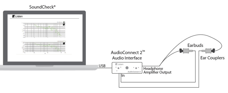
Finished products such as earbuds are simple to measure. A MEMS headphone can be tested in exactly the same way as any other headphone using an audio test system with a head-and-torso simulator (HATS) or ear couplers, and a Bluetooth interface if needed. Figure 1 shows a typical headphone test configuration that could be used for testing a pair of wired MEMS earbuds. The test method is simple. The test signal is played through the headphones and captured using a HATS or ear couplers, where it is sent to the computer for detailed analysis of frequency response, phase, distortion, and more.
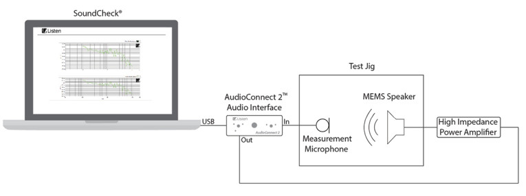
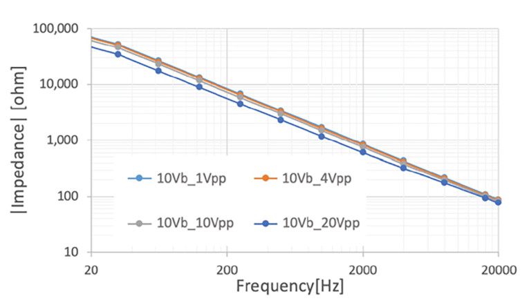
Raw MEMS drivers are more complicated to measure due to their small form-factor and power requirements. That said, the basic measurement principles are the same as any other driver; the complexity is in the fixturing. In addition to an audio test system (interface plus software), a typical configuration requires an ear simulator coupler to capture the signal, custom fixturing to hold the MEMS driver in place, and a special driver circuit for the MEMS device. Piezo-MEMS devices have a very high input impedance and draw very low current. Typically, MEMS speaker manufacturers provide their own driver circuit to deliver voltage bias and boost converter to step up the voltage, and this should be used for making measurements.
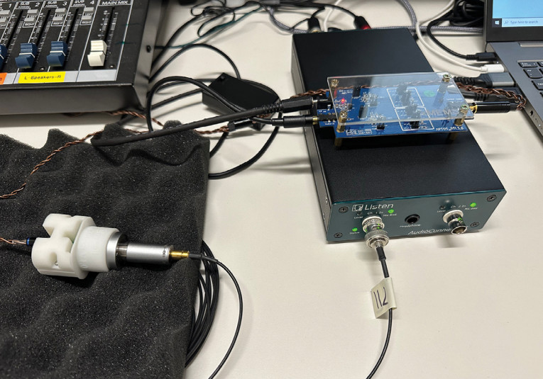
Figure 2 shows a schematic diagram of the test configuration used to measure a MEMS speaker, and Photo 1 shows the test jig, coupler, and charge amplifier in more detail.
MEMS Measurement Results
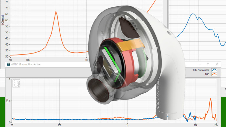
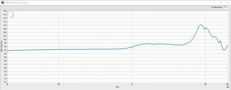
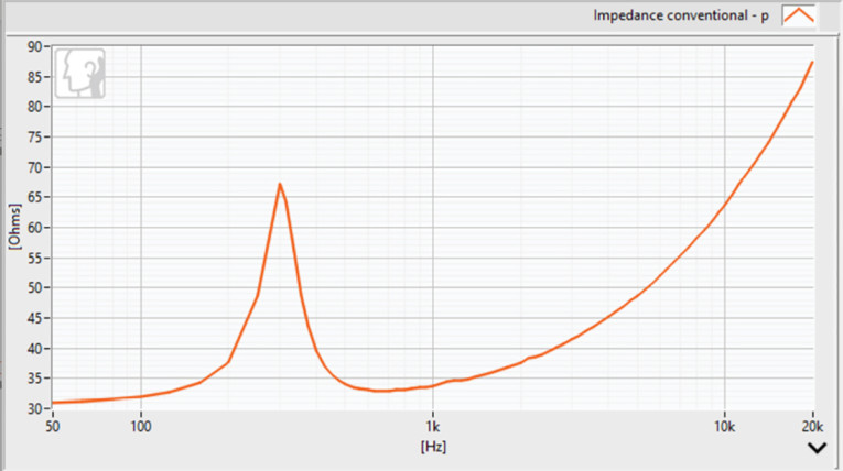
The frequency response, shown in Figure 3, is very flat up to 1kHz. In the higher frequencies, there are a couple of resonances—one due to the piezoelectric material and the other due to the resonance of the coupler, which simulates the human ear. MEMS speakers exhibit fewer resonances than conventional speakers due to the simplicity of their design. They have fewer moving parts than a conventional speaker and consequently fewer break-up modes. Once the device is measured and the resonances known, they can be accounted for in the product design to minimize their effect.
The higher frequency resonances in the MEMS speakers are actually easier to design around as they are out of the most sensitive range of the human ear. Perhaps future development might result in these resonances being moved out of the audible range altogether. Naturally this information also provides useful data points for refining MEMS speaker models, which will, in turn, help design better speakers.
It’s advantageous to use frequency-normalized distortion measurements rather than conventional distortion measurements when measuring the total harmonic distortion (THD) of MEMS speakers or any other loudspeaker, as the difference can be quite significant. Normalized distortion measurements compare the harmonic levels to the fundamental level at their measured frequency before their ratio is plotted, rather than the fundamental level at the excitation frequency. This provides more accurate results as it removes the effect of the non-flat frequency response from the THD. This makes it easier to see the peaks in the THD response independent of the peaks and dips in the fundamental response, and easier to set limits.
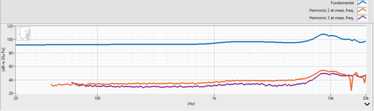
Figure 6 shows harmonics plotted at their measured frequency (not at their excitation frequency) along with the fundamental for the Montara Plus piezo-MEMS speaker. You can see that the fundamental bumps at the high frequencies are superimposed on the harmonics.
In Figure 7, the orange line shows the THD calculated at the conventional stimulus frequencies (THD) and the blue line shows the normalized THD, calculated at the measured stimulus frequencies. Removing the effect of the non-flat frequency response from the distortion makes it easier to see the peaks in the distortion response independently of the peaks and dips in the fundamental response.
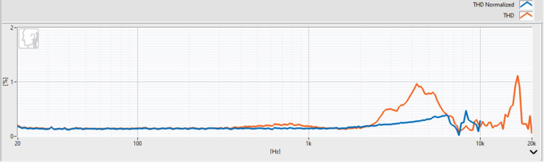
It shows that the THD is very low up to 10kHz. As with the frequency response, an understanding of the high-frequency distortion enables it to be minimized with good product design. It is clear from the normalized measurement that there is a high Q at resonance between 8kHz and 9kHz, but apart from that there is very little distortion, so design efforts can be focused on planning around that one peak. If a design was based on the conventional distortion measurements shown by the orange curve, time would be wasted trying to solve the distortion between 4kHz and 5kHz on the graph that does not really exist.
Conclusions
MEMS speaker technology is rapidly evolving to meet today’s mobile audio requirements. The simplicity of construction results in features such as flat frequency response, linear impedance, and predictable distortion that facilitates their design into consumer electronics products.
Accurate audio measurements of both raw drivers and finished goods are essential to develop and refine models, which are still in their infancy compared to more established driver technologies. While finished goods containing MEMS devices can be measured in the same way as their conventional counterparts, raw MEMS drivers require custom fixturing and an appropriate amplifier. With these test components, they can be measured in the same way as a conventional driver.
The distortion in a MEMS speaker is typically highly focused around one frequency, and normalized THD, often called frequency normalized distortion, is highly recommended over conventional or non-normalized distortion measurements to accurately evaluate this distortion. aX
This article was originally published in audioXpress, June 2024
About the Authors
 Steve Temme is the founder and President of Listen, Inc., manufacturer of the SoundCheck audio test system. Steve founded the company in 1995, and over the past 29 years the company has remained on the cutting edge of research in audio measurement, introducing many new measurement algorithms and techniques. In recent years, Listen’s product development focus has been on creating the algorithms, interfaces and test methods to measure today’s newest devices including MEMS speakers and microphones, as well as automotive audio and various wireless and cloud-communicating devices. Prior to founding Listen, Steve worked for many years as an acoustic test and measurement applications engineer at Brüel & Kjær, and also as a loudspeaker design engineer at Apogee Acoustics. He holds a BSME from Tufts University, has authored numerous papers on acoustic testing, and has lectured extensively throughout the world.
 Michael Ricci is the Senior Director of Electroacoustic Engineering at xMEMS Labs, in Santa Clara, CA, where he built and maintains multiple test labs to support Piezo-MEMS μSpeaker integrations for consumer hearables and professional audio products. His technical background includes 25 years of semiconductor device testing with a focus on MEMs transducers. Michael has held Senior FAE and Principal Electroacoustic Engineering positions with Bosch Sensortec (Akustica MEMs Mics) and Knowles Electronics supporting strategic accounts with MEMs microphone and balanced armature integrations. Industry affiliations include Acoustical Society TAG voting member, the Audio Engineering Society (AES), the National Association of Music Merchants (NAMM), and the American Society of Composers, Authors, and Publishers (ASCAP).