By Daniel Knighten and Eric Hodges (Audio Precision)
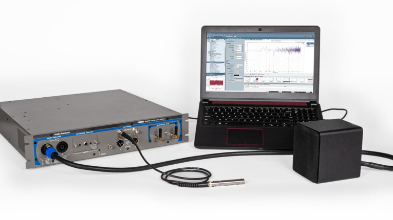
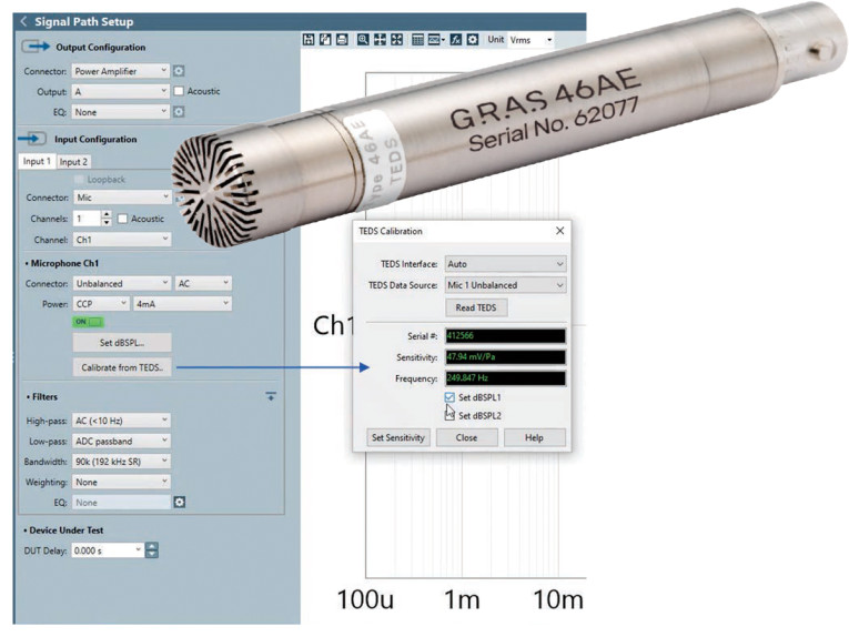
In the simplest of terms, developing the manufacturing test strategy for a given product, in the case of this discussion, a speaker, can be viewed as the need to balance the cost of test against the cost of failure. However, this simple concept points to what can be a far more complex equation involving several variables for both “cost of test” and “cost of failure.” In the former case, cost is measured in both time, as defined by setup requirements (e.g., the APx 517 analyzer and the GRAS microphone seen in Figure 1), test methods, and money, primarily system cost. Assessing the cost of failure ranges from the expense of warranty repairs and product returns to the more nebulous, but still very real, impact to brand (witness the power of the 1-start review). In this article, we review these manufacturing test considerations and then speak to applied strategies for efficient testing.
Manufacturing Test Objective
The goal of a manufacturing test is to ensure that the products manufactured, and ultimately shipped to retail outlets or directly to customers, meet their design specifications and perform as intended. Unfortunately, uncontrolled variability or tolerances in materials and manufacturing processes can directly, and negatively, impact the ability to achieve this goal. So, the fundamental question is: What is the most effective way to test products to ensure they meet specification?
On one end of the spectrum, absolute quality assurance is attained via full functional testing of the device. In such an approach, the test strategy is defined by the product’s functional specification and each device produced is tested to ensure every element meets the specification. In the context of an audio device, all connectors, speakers, and microphones are exercised according to their performance specifications and verified to work correctly. It goes without saying that this test strategy is quite expensive, in the equipment and fixturing required, as well as the significant amount of time devoted to testing during manufacture.
At the other end of the spectrum is simply not testing at all. This approach is aligned with devices that are so inexpensive that the investment in testing and quality control is not warranted. In the case of such products, the user or customer is, in effect, the quality control process. Customer rejections or field failures become the signaling mechanism that there is a quality problem.
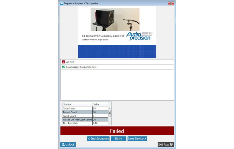
Between the two extremes of full functional test and no test at all lies the complex analysis that is the comparison of the cost of test and the cost of failure (or, conversely, the value of quality). Depending on the value of a product (and/or its brand), it may be critical to ensure that no sub-par products reach end customers using a Pass/Fail routine, such as the APx example depicted in Figure 2. The determination of just how critical that is, or isn’t, will define the quality standard for the manufacturer and ultimately establish the test strategy used.
When and Where to Test
Rare is the modern device that is 100% assembled and manufactured from only in-house materials—most come together as components, and potentially sub-assemblies, from many suppliers that are then assembled into the final product. If testing is reserved until the device is fully assembled—referred to as final, or end-of-line, test — any failures can result in the added expense of re-work or possibly in a complete scrap of a finished device. If components and sub-assemblies are tested but no final check is performed, a defective product may end up in the hands of a soon-to-be dissatisfied customer. How can a product assembled entirely from good components fail? Mis-assembly and damage during manufacture is the likely culprit.
As with the test spectrum discussion earlier, answers to the question of “where to test?” range from every point in the supply chain and manufacturing process to not testing at all. Returning to the initial analysis of cost-of-test vs. cost-of-failure that determined a product’s quality standard and test strategy, if that process determined that some manufacturing test must be performed, “where to test?” is often best determined by where the failures are occurring.
Or conversely, by referring to the axiom “a test that never fails is not useful.” With this in mind, many manufacturing organizations or quality teams start with extensive testing during the development process for a product. Frequently referred to as Engineering, Design, and Production Validation Tests (EVT, DVT, and PVT, respectively), such steps are used to optimize where and for what audio test should be performed. The goal of this testing is not just to confirm the performance of the design or even to qualify components but to determine if incoming material quality and in-house manufacturing processes call for more, or less, testing in specific areas.
The Lab vs. the Line
One common area of tension is the desire to directly correlate audio measurements made on the manufacturing line with those made in the product development lab. This is an inescapable tension because measurements made during product development — seeking to first validate, then fully characterize design performance—usually take far more time to perform than can be tolerated, or afforded, within manufacturing.
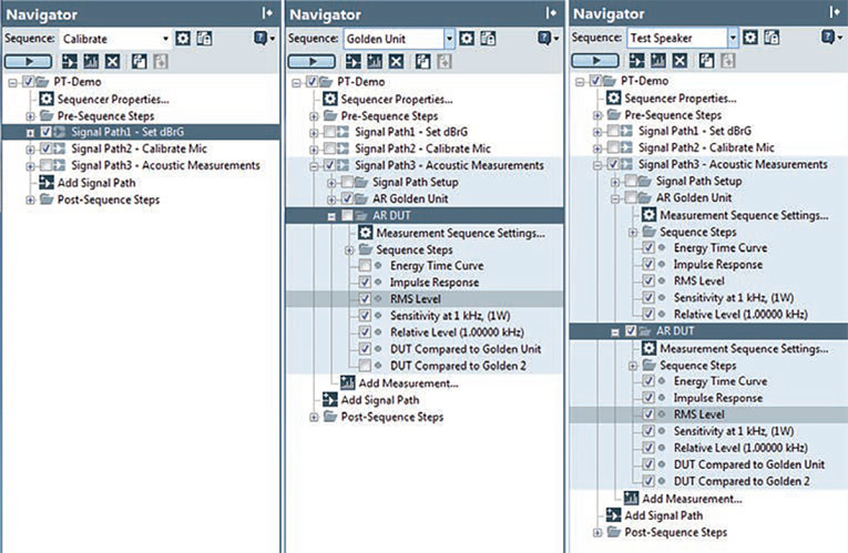
As a prime example, it can be described as trying to compare the speaker’s free-field frequency response to the same speaker’s response inside a compact test cell. While the direct comparison of R&D measurements to QC measurements is often difficult at best, using similar test systems, or least systems sharing a common software and measurement methodology, such as the APx software operating screen shown in Figure 3, can go a long way to reducing or even eliminating this tension.
Beyond the use of a common test software, the single best strategy to addressing this tension and closing any gap is the development of a test standard and the use of reference (aka, “golden”) units. With this approach, known good units are measured in the development lab as well as at each manufacturing location. These measurement results are then compared and correlated. In scenarios where test results cannot be directly compared (e.g., because the acoustic test fixtures are different), the development of transfer functions that adjust for the difference between different fixtures are a possible solution. However, a separate transfer function for comparison between test fixtures must be created for each product (i.e., specific model) as a transfer function is only valid for a given device.
Speaker Manufacturing — What to Test
In the case of speakers, as well as earphones and balanced armature drivers, testing the device at one frequency provides only minimal utility. More commonly, and more effective in determining performance, these devices are swept across a range of frequencies of interest. To reduce test time in a manufacturing environment, and since uncorrelated noise is not a useful measurement on a speaker driver, the frequency sweeps can be very fast, with a few second-long sweep usually enough. When testing a speaker driver, it is useful to examine the device’s acoustic response and the impedance function. The combined results of these two measurements will essentially reveal whether the system is performing to specification or not.
Returning to the discussion on where/when to test, incoming inspection of raw speaker drivers can be easily performed via an electrical-only measurement of impedance. Since any deviation in mass of the cone, or compliance of the suspension, will shift the impedance curve—particularly at the frequency of the resonant peak—this approach can be used to quickly eliminate devices with common assembly errors before they end up in a finished product.
This method — measuring just impedance — significantly simplifies the incoming test requirement, as it removes the need for an acoustic test box or measurement microphone, and considerably simplifies test setup. For best measurement repeatability, impedance should be measured at small signal levels, where the motion of the driver is within the linear, piston range of motion.
It is worth noting that this leads to a common disconnect between R&D and manufacturing, so it is worth remembering that this technique is focused on incoming or pre-assembly tests, not necessarily final tests.
In the latter, drivers are usually measured at high signal levels, to test the driver through its full range of motion. However, the impedance curve of a driver at high signal levels cannot be compared to the typical small signal used when calculating Thiele-Small (T-S) parameters, the more common measurement made in R&D.
Modern audio analyzers can usually measure all the important parameters of a speaker in a single fast sweep as seen in the APx setup menu (Figure 4). With a measurement microphone, such as the GRAS 46AE, and an electrical connection to the analyzer amplifier, a speaker’s acoustic frequency response and distortion can be verified — along with the impedance and resonance, rub and buzz, high-order harmonic distortion, and even polarity — in a single test.
Statistical Process Control
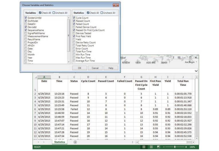
Beyond the very clear manufacturing test objective, in conjunction with a defined quality standard of limiting or eliminating the shipment of non-compliant product, production-line tests can provide added value via the tracking and analysis of test results (beyond simply recording pass or fail). The collection and storing of measurement data allow for a variety of analyses. (Figure 5 shows an example APx statistical analysis data base screen.)
Any field failure can be audited or traced against the measurements made during manufacturing to better understand how manufacturing tests can be modified to check for a previously unidentified failure mode. It is also possible the device passed the final test, but only marginally, and the pass/fail limits should be adjusted. (Remember the axiom about a test that never fails — measurement data can be used to identify such tests, possibly allowing for their removal to save test time.) Perhaps the device passed but only after extensive retesting, indicating the device had erratic behavior and policies on retest need to be evaluated. Even as devices pass, it is useful to examine trend data to detect drift in materials and tolerances to preempt future quality issues.
Conclusion
The technical details of the measurements made in manufacturing are directly related to a given product’s value proposition, along with the organization’s overall quality standard, and ultimately, their brand. Is the product positioned as a high-end or luxury item or as a value-oriented product? How is it priced? What is the cost of a field failure (whether determined by the cost of managing return and replacement, in damage to the brand, or both)?
Answers to these questions help define the budget for manufacturing tests and quality control. Will every unit assembled receive a full functionality test or will only basic functionality be checked? Maybe only incoming tests of common failure components is appropriate or will every unit be tested or will a sampling approach be used for manufacturing test?
With test objectives and a budget set, it is then possible to define the technical requirements of the measurement process. With a minimal test budget, just stimulating a device with a single tone and recording output level and THD+N may be the answer. For higher value items, and an associated larger test budget, it may be better to use multitone, continuous sweep, or another fast measurement technique to characterize a device over a more complete functional profile or various use scenarios. Ultimately, the technical requirements for quality control tests are the product of overall quality standards, and the potential cost of field failures that defined those standards. VC
This article was originally published in Voice Coil, April 2021.