Photography: Dennis Dudek

Jan Didden: Joachim, we ended the first part of our conversation about your adventures in phono stage land with the discussion of the Flexible Phono Stage. But you still were not satisfied?
Joachim Gerhard: No, I wasn’t. In the best case of the Low Z version of the hybrid INA two op-amps are in series with the signal so with the best devices on the market at the time like the OPA1611, OPA211, AD797, LT1115, LT1028, LME49990, and ADA4898 ( yes, I tried them all), it did not get any better than 1.45nV/rtHz. The next step was paralleling op-amps and that was a step forward. No oscillation like the one that my friend had encountered with the INA163. The most extreme case was coined “Dolphin“ and had four plus four AD797s in parallel. It had 0.7nVrtHz, very good for balanced, very expensive to make (those low noise chips are not cheap) and still not the theoretical minimum. Guess what, the next step was going discrete in the input stage so my Discrete INA was born. I decided on a cascoded FET input stage. The devices I chose are optimized for MC duty and are still available as NOS [new-old stock] although not produced any more. They are the Toshiba 2SK170BL and 2SC74BL. Linear Integrated Systems produces substitutes for obsolete Toshiba devices, and the LSK170/LSJ74 works perfectly here, so let’s hope that these excellent designs are not lost forever. The same is true for low noise BJTs. Most of them are not produced any more but some medium power devices that are not explicitly designed for MC inputs are still available new [5].
FETs have quite a high and nonlinear input capacitance and cascoding them with BJTs reduces input capacitance much. It also has the advantage of lower distortion because the FETs are driven at nearly constant voltage and current. PSU suppression is also better with cascoding and I feed the cascode from a well-designed constant current source that reduces PSU ripple even more. The constant current sources can be adjusted so voltage at the collectors of the cascode BJTs can be held constant and equal in the positive and negative amplification chain. Voltage at that point should be set at around half of the PSU voltage to optimize dynamic range. For a ±12V supply, 5V to 6V is fine. The input FETs are held under 3V then and this is not ideal for lowest distortion (7V would be better) but for lowest noise this is the best solution because under 3V no hot carriers develop that give rise to flicker noise. The distortion is taken care of in the feedback arrangement.
The cascode and current source BJTs are the old faithful 2N4401 and 2N4403. They are not bad in this application at all because they have low base spreading resistance ( Rbe = 40Ω, extremely low values are not necessary here because noise in the cascode is not correlated with the input FETs) and low output capacitance. Best of all they are still made today in quantity and very affordable. They do not have high Hfe but in a cascode this has the advantage of high early voltage. When you are into swapping mode and want to try alternatives [see the sidebar on page 44 in Part 1 of the article in audioXpress, September 2024].
JD: You probably need to match those devices to some degree?
JG: No, Hfe and Vbe matching is not necessary in my circuit because the current sources are adjustable. They also compensate for Idss differences in the FETs. I found that the P channel variety has lower Idss usually and matching them would be time consuming and not fun at all. You would literally have to buy hundreds to have some success because FETs have much higher spread of parameters than BJTs do. In my design you can simply use the FETs and the BJTs straight out of the tube or any other package they come in. The parallel symmetric design has also the advantage of distortion cancellation of second harmonic, the major source of distortion in a single-ended FET—BJT cascode, while third harmonic is low in a FET — BJT cascode anyway.
So, we have a fast, low noise, low distortion balanced input stage. It’s time to discuss the rest of the circuit. First let’s look at the circuit diagram (Figure 8a). A detail that I have not discussed when explaining the input stage is the unusual biasing of the cascode transistors. It is simply a resistive divider fed by constant current sources. This arrangement is called a ground referenced common base stage. It is a rare sight, and I first spotted it in a design by Hugh Dean of AKSA fame. It has several advantages: simplicity, low noise because a separate bias source with potential noise is not necessary, and a measure of current feedback that stabilizes the gain, lowers distortion and raises the bandwidth a bit at the cost of a bit of gain.
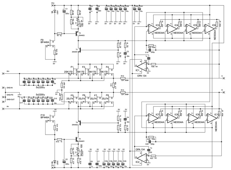
Actually, I have not tried the alternative separate bias version because the circuits worked beautifully right away, so if you think separate bias is better, try it at your own risk. Be careful with the lead lag compensation though. Without the current feedback action of the ground referenced bias the already tremendous gain goes sky high and other components may be necessary for compensation to avoid wild oscillation.
Considering how long I needed to get the circuit correctly compensated for stability I recommend this practice only for experienced builders who have some background in feedback theory. I found that this circuit was somehow hard to simulate so the chosen values were optimized by feeding a scope with a differential signal from the two shunt feedback op-amps. The values given result in a perfect 10kHz square wave without any overshoot. Frequency response in this arrangement is limited to 200kHz -3dB with a shallow slope to avoid high-frequency interference. The next stage after the input plus lead lag compensation consists of op-amps in a shunt feedback arrangement. They perform a current in — voltage out conversion somewhat limited by the resistors in the ground referenced common base stage.
JD: Why are there four op-amps in parallel in this stage?
JG: We go for the lowest noise and that means we have to make R2 small so when we want a gain of say 36dB, R1 gets small too. Besides making noise low I also like to make the overload margin as high as possible. An average op-amp can drive 20mA clean so four of them can drive 80mA. Brute force paralleling is usually not recommended but putting 47Ω resistors at the output isolates the op-amps well enough and this circuit works without problem. Each leg can drive 9.92V in a 124Ω resistor so we get 19.84V total after the differential stage. This is an insanely high overload margin.
If we use a cartridge with 0.5mV output at 5m/sec and we assume that 50m/sec can be cut at certain frequencies, we have a maximum input voltage of 5mV. Add to this a gain of 40dB for example and the maximum output voltage is 500mV. That is a relation of 19.84/0.5 = 39.68 leading to an overload margin of 32dB! 50m/sec does not exist in reality, but some records may have surface blemishes like scratches and dirt that can send transient-rich high energy pulses into the system. John Curl told me he measured transients up to 500kHz!
Anyway, I found that phono stages with high overload margin sound better and can handle scratches much better making them audibly “shorter“ and separating them in the sound field from the music. The scratches coming from the left and right loudspeaker plane and the music stand “free” in three-dimensional space provided your speakers are up to the task.
You may ask why I do not use one op-amp with higher current drive ability like the OPA551. The reason is that my arrangement is more flexible in op-amp choices. So, if you do not like to use the NE5534A you can put in your favorite specimen. I tried LME49710 and OP27 with success so the more modern OP227 should work too. If you have a weak spot for FET designs you can try OPA134, OPA1641 or the even better spec’d OP827 and ADA4627. Be careful when the gain-bandwidth product goes much over 20MHz because the circuit could start to oscillate. OPA827 can be used in the servos too. DC offset will then go down from 1mV of the OPA134 to less than 0.1mV.
Coming back to the function of the circuit the result is tremendous gain that the late Allen Wright of Vacuum State used to call “scary.” Again, I am using an old and well-known part here: the NE5534A, this a selected version ( Noise + DC offset) of the NE5534 that started life more than 30 years ago as the TDA1034 from Signetics. Why this old war horse? First, it is a very low distortion part, even today and I use only the basic transfer linearity that is excellent in the shunt feedback arrangement used. Second, it has low current noise for a BJT input op-amp, four times less than the old standby LME49710 and derivatives. This is necessary for low noise in the current to voltage conversion. A FET op-amp could be used as mentioned but results were fine. Third, it has a 10MHz gain– bandwidth product and this is just right for the compensation used. The faster LME49710 worked too but I did not have success with the very fast AD797, for example.
It (the NE5534) has some issues with DC offset but the servos take care of that offset as well as the 5V to 6V bias from the input stage. A compensation cap is fitted over the 100kΩ resistor for stability and optimum time domain behavior. Feedback resistors both from the positive and the negative side go to R2 and our discrete INA is complete. Simply combining the outputs would not work because we would only hear the common mode signal that is superbly low. I know it because I tried it. What we need is a differential stage that extracts the amplified input signal. It occurred to me that this stage could also do the RIAA differentially. That would save an additional output stage and a differential RIAA done right has a lot of advantages too.
JD: If memory serves, you also designed a phono stage with the fully differential OPA1632.
JG: Correct — the OPA1632 is differential in, differential out and ideal for this purpose. The circuit is shown in Figure 8b. It has very low voltage noise, low distortion and high bandwidth and can drive low impedance. A differential stage could be built with separate op-amps too, but I prefer this integrated solution. The layout can be done very compact, and performance is excellent.
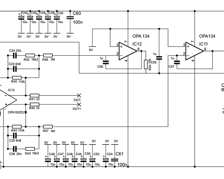
For the RIAA I use a shunt feedback arrangement. It has many advantages that were described by John Linsley Hood [6]. I simply will quote him here and add some comments: “Shunt feedback layouts can also give a precise match to the RIAA specification, which a series feedback circuit, as it stands, will not. This is because any series feedback layouts having a feedback limb which decreases in impedance with frequency will tend to unity gain, whereas the RIAA specification stipulates a gain curve which tends to zero gain. Unfortunately, in many preamplifiers of commercial origin, which use series feedback RIAA stages in order to obtain lowest practical (input short-circuited) noise levels, this error is ignored, even though its effect can easily be seen on an oscilloscope and the tonal difference it introduces can easily be heard by the listener.“
As JLH continues, ”The effect of this is to alter the relative character of the noise given by these two systems, so that the noise from a series-type circuit is a high pitched hiss, while that from a shunt-type circuit is more of a low pitched rustle.“ And finally: “There are also a few other advantages offered by shunt-feedback RIAA circuits. Of these, the most important, in practice, is that they are largely immune to the very short duration input overload effects, which can be caused by voltage spikes in the cartridge output arising from dust and scratches on the surface of the record. These short duration overloads can greatly exaggerate the clicks and plops which are a nuisance on vinyl disc replay. Also, they have, in theory, a lower level of distortion.”
Here we have the overload theme again. Some beta testers of my design suggested a passive RIAA at least for the treble 75µsec time constant. RIAA precision with passive is as good as shunt-active but I refused because that comes with an overload penalty. Even doing only the treble passive would worsen the overload margin by 14dB and increase distortion due to less feedback in the treble. See Douglas Self’ book Small Signal Audio Design for an in-depth discussion about the advantages of active RIAA stages [7]. What is true for transistor design may not be true for tube design. Tubes running on very high voltage have a huge overload margin by default so I would see no problem designing a good sounding passive RIAA with tubes but that is not my forte.
The differential nature of the RIAA has also the advantage that component tolerances average out somewhat but for best common mode rejection caps and resistors should be matched. 0.1% resistors are recommended and easy to get. Good quality caps with 1% tolerance are available in Polypropylene and Styroflex and actually the values chosen give 0.1dB RIAA precision with 1% parts. For best common mode rejection this is not good enough. 1% tolerance gives a CMR of 40dB, a bit meager but still useful. I would suggest that you select quadruples of caps for the positive and negative chain and the right and left channel. It is not so important that they have the absolute correct value, 1% off gives still ±0.1dB accuracy, but both channels and plus and minus chains should match. CMR will benefit, so does three-dimensional imaging and focus. The FPS finishes off with two 22Ω resistors that drive the balanced output and a differential servo that holds the DC offset between non-inverting and inverting output low.
So here we have it: A thoroughly modern state-of-the-art phono stage that you can build with parts that are readily available. I cannot hear a loss of information with this circuit, instead the sound is very natural, clean and dynamic but your ears will be the final arbiter of course. At least from the standpoint of objective performance this stage is hard to better.
Photography: Dennis Dudek

JD: Joachim, thank you so much for the opportunity to talk to you about these fascinating concepts and designs!
JG: My pleasure Jan! If I may add some closing thoughts — this would be a good moment to express my heartfelt thanks to many people who have, over the many years, contributed to my understanding and ideas for designs — without all that help and inspiration, many of them simply would not exist. Without being complete, I’d like to mention the late Allen Wright, Salas, Ovidiu Popa, Ward Maas, Sigurd Ruschkowski, Jan Didden, the late Scott Wurcer, John Curl; and for those not mentioned, you know who you are. I also learned a lot from books written by Douglas Self, Burkhart Vogel, and John Linsley Hood.
Finally, a suitable power supply for this and other designs would be one of the variants of the Didden/Jung super-regulators [8]; a suitable design is available from the diyaudio store. aX
Read Part 1 of this interview with Joachim Gerhard
References
[5] “Low Noise Designs: HPS 4.1” DIY Audio, www.synaesthesia.ca/LNschematics.html
[6] J. L. Hood, Valve and Transistor Audio Amplifiers, 1st Edition, Newness, ISBN 978-0802839947.
[7] D. Self, Small Signal Audio Design, 4th Edition, Routeledge, ISBN 978-1032366258.
[8] J. Didden and W. Jung, Super Regulator, The DIY Audio Store,
https://diyaudiostore.com/products/super-regulator
This article was originally published in audioXpress, October 2024


