Photography: Dennis Dudek

In this interview with Joachim Gerhard, we discuss design considerations and circuit topologies for low noise phono preamps and several of his realizations. Because of the extent and valuable details in the conversation, we will publish a second part of this interview where Joachim further develops his design ideas with a discrete instrumentation amplifier topology.
Jan Didden: Joachim, you are mainly known for your work in loudspeakers. What is often underexposed is your significant work related to electronics such as phono preamps and power supplies. We agreed that in this interview we would talk about that. Although I realize that no conversation with you would be completely free of speaker things! Let us start at the beginning—when did you get interested in audio technology?
Joachim Gerhard: I can’t remember exactly, but when I was maybe 12 years old, I started to remove speakers from old TV sets or radios found on scrapyards, put them in a box and used them to party!
This was in the 70’s, all my friends did it. There was no Internet then and it was a lot of trial and error. I must have done something well because I got a bit famous for my speakers. I don’t know why, but I built speakers and speakers and speakers. And I tried all kinds of things, like a transmission line, a horn, open baffle, or whatever. It started very early in me, I wanted to build the next loudspeaker. And the next. And the next. It’s hard to explain, but I had so many ideas…
JD: But did you have the technical background at that time?
JG: It started with Thiele and Small. 1973, I think. It was the first time I understood that loudspeakers can be simulated. Until then, you took a speaker, put it in a box, and lived with what came out of it. But with these [Thiele and Small] parameters, you could optimize the volume or go for the best bass extension, or whatever. I always liked to read, so I read and read about speakers, everything I could put my hands on.
I started to travel and visit all those pioneers of the time. I travelled to the USA and met Paul Klipsch and Siegfried Linkwitz. I spent time with Malcolm Hawksford at Exeter University in the UK. It was a great time of learning and development.
Later I went to study telecommunications, you know, a real education my mother could be proud of. But my heart wasn’t in it, and I stopped after a few years and started an apprenticeship in carpentry. After that I studied furniture design in Kassel. I had no idea how to go professionally into business at the time. But in 1983, some friends and I built up a shop in Hannoversmünden, a small town near Kassel, where we combined modern art with HiFi. Or at least that was the plan. But it didn’t work out; some people were interested in the sound and others in the shapes, but not both.
JD: So there you are, living a life in audio. How did you get active in the electronic side of it?
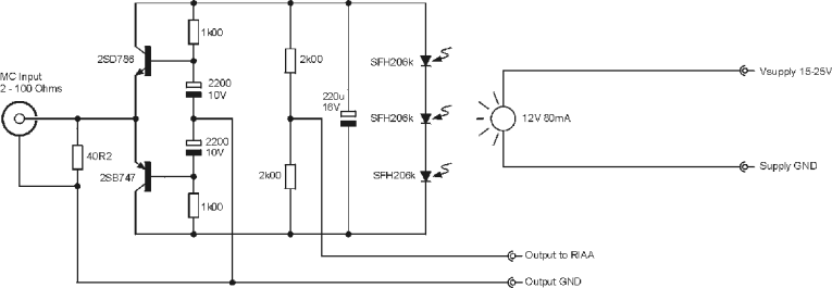
JG: The interesting thing is, when I started Audio Physic, the first product was not, as many think, a loudspeaker, but a phono preamp! In my first design I pulled out all the stops—it was a parallel symmetric common base stage without global feedback and floating battery supply. I got the circuit idea from Wireless World without knowing it was based on a Marshall Leach design of several years earlier. Eventually it morphed into the LC Audio MC Pre with a twist of a “light” supply (Figure 1).
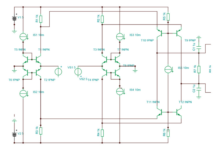
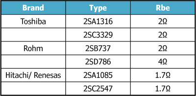
The first design was a balanced MC stage that also had parallel symmetric common base stages. It is sometimes known as a zero-input impedance stage, but being an open-loop design it actually has around 10Ω to 20Ω input impedance, depending on the transistors used and the idle current setting (Figure 2). I used the MAT02 and MAT03 transistors in a desire to use “the best,” but I soon learned that they are not particular symmetric regarding matching of P and N devices. There are other BJTs that have lower noise, better matching, and higher and more linear Hfe. (Table 1 lists some candidates.) The critical parameter for low voltage noise is, as you know, Rbe, the base spreading resistance. Low voltage noise is important for an input stage for MC cartridges because they have a low source impedance. It can be as low as 2Ω and up to 50Ω.
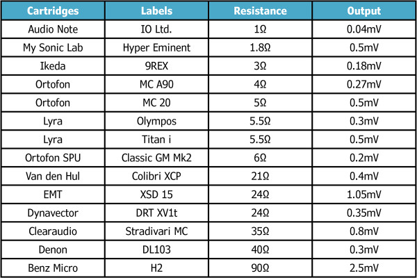
A relatively high impedance combined with low output voltage is not a good start for a low noise result because the Johnson noise of the cartridge adds to the noise of the phono stage. Ideally, an MC cartridge should have the lowest possible impedance and the highest possible output voltage so a cartridge with low impedance and very low output voltage is a challenge too because the phono stage has to make up the gain and loses signal-noise ratio in the process. (Table 2 lists some common and not so common examples.) You can draw your own conclusions, but I find the Hyper Eminent outstanding in relation to impedance versus output voltage. There must be some extremely strong magnets at work there. In practice, a lot of issues play a role for the potential sound, not the least the choice of diamond cutting and grinding, the suspension and mechanical design in terms of rigidity and damping.
I am using Lyra cartridges most of the time and get very quiet results with the circuit I eventually got to, even on my 100dB sensitive MPL loudspeaker system. The hum of most power amps, especially the tube variety, is generally higher than hum and hiss from my phono stage.
JD: A recurring issue with these stages is the desire for DC coupling, because at these low impedances, AC coupling would require huge capacitor values. How did you solve that?
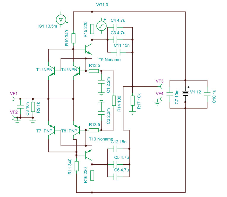
JG: DC current through the cartridge is to be avoided because it generates second-harmonic distortion and in a worst-case scenario can destroy the delicate windings. Vbe is a very weak function of idle current so making a DC coupled input and output comes with considerable complexity. DC canceling in the input stage comes with a noise penalty and additional circuitry that is against Occam’s Razor, the notion that the simplest solution that does the job is often also the best. I did design the Ultra Low Noise ROSI that avoids DC in the cartridge with a floating supply. A similar circuit was described by [Paul] Rositter in audioXpress [1]. Unfortunately, it needs a big electrolytic caps to ground and is not DC coupled at the output (Figure 3). Nevertheless, circuits like that can sound excellent with careful component selection.
The next logical step was to try common emitter circuits or emitter followers, with and without bias cancellation. Both circuits have the advantage of low DC at the input because only a little current is flowing into the base. Take that idea further and FETs are unavoidable. Compared to BJTs they have nearly zero gate current, so DC coupling is a breeze. Their main disadvantage is a quite high 1/f noise corner frequency, so they are noisier in the lower ranges of the frequency spectrum. In practice, I found that it is less of a problem because the human ear is not very sensitive at lower frequencies and the rise in noise is very shallow in modern, optimized devices. Higher up the frequency range the noise from a FET has a softer “benign“ tone so low noise designs with FETs can be done.
The first design I did was an instant hit and is now known as the High Z MPP. Several people build it with success. It is simple, high performance, and elegant. It is a folded cascode, open-loop design. Noise can be brought down to 0.3nVq/Hz if eight FETs are used. Distortion is -100dB at 2V output theoretically (I measured -90dB in practice) and frequency response is wide ( -3dB over 5MHz; Figure 4).
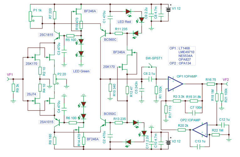
Whatever I tried, I could not improve distortion with an open-loop design, so this is at least for me the limit what can be done with open-loop designs. That notion was confirmed when I saw the measurement of “The Grail,” the Van den Hul phono stage. It uses an open-loop input circuit and was designed by Jürgen Ultee, an expert on measurements.
When you belong to the chosen few that can hear distortion at less then -90dB and you are not afraid of feedback (highly optimized, that is) I have a gift for you.
The FPS — Flexible Phono Stage
So NFB (negative feedback) was on the agenda. Strictly speaking an open-loop design also needs feedback to be stable, in this case a resistive element that does “current feedback.” The difference to NFB is that negative feedback returns a part of the output signal to the input for error reduction. Some designers I talked to and that I respect told me that part of the input signal could be lost in the process especially considering the tiny signals involved and that the distortion gets lower but more complex in spread. The result would then be a loss of acoustic information leading to a flat “papery” soundstage and a loss of micro information making the sound sterile, analytic and hard. My head was humming, and I calculated the numbers even while in the car and in my dreams.
Considering an output of 0.5mV at 5m/sec and 20dB headroom there still can be -60dB “bottom room” so the lowest encoded signal would be 0.5µV. Considering 40dB of feedback we have a correction signal of 5nV, not much. The only way out I found was finding a topology that has superb low-level resolution, building something, and then listening to see if I could detect a loss of information compared to the open-loop circuits I had already built.
I worked in the High-Tech industry from 1985 to 1989 and knew there was a topology that was optimized to amplify tiny signals in the presence of noise and hum: The Instrumentation Amplifier or INA in short. It is for example used to detect brain waves. In its basic form it consists of three operational amplifiers [op-amps] that are connected in a certain way. One of the integrated solutions at the time was the INA163 from Burr-Brown (Figure 5).
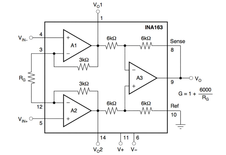
If you want to know more about INAs you can download A Designers Guide to Instrumentation Amplifiers [2]. On the first page you can find the statement: “An Instrumentation Amplifier is a device that amplifies the difference between two input signal voltages while rejecting any signals that are common for both inputs. The in-amp therefore provides the very important function of extracting small signals from transducers and other signal sources,” and that is exactly what we want. The first circuit I tested used the INA163 at the input. It certainly sounded great with a lot of dynamic slam. I could not detect a loss of information, so this was a very encouraging result. One of the disadvantages of an integrated INA is that the internal feedback resistors are fixed. In the case of the INA163 they are 3kΩ.
The gain equation of an INA is Gain=((2×R1)/R2)+1 so for a gain of 36dB R2 ends up being 80Ω (Rg in Figure 5). Unfortunately, that resistor is in series with the signal, so its Johnson noise adds to the noise of the active stages in the INA. In this particular case, the ca. 1.3nVrtHz of the 80Ω resistor adds to the 1nV/rtHz noise from the active stages in the INA163. One solution is to raise the gain and then put a resistive divider at the output. That would make R2 small but feedback is less, so distortion goes up and bandwidth goes down, quite a waste of quality. Another way is to parallel several devices to lower the voltage noise. This arrangement is called a Faulkner Circuit. A friend of mine tried that with the INA163 but he could not get that circuit stable.
JD: That’s often the issue with those integrated solutions, isn’t it? They are great for most purposes but if you have a special need, like for a phono stage, they have limitations in the practical area.
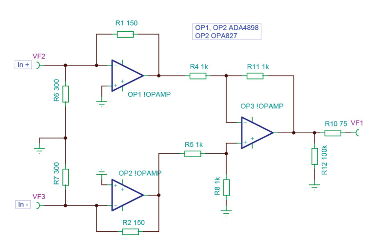
JG: Yes, and to circumvent this situation I developed circuits that use three separate op-amps, so I have a wider choice for R1. I designed a Low Z (Figure 6) and High Z (Figure 7) version, and they worked beautifully. Again, the Low Z version had a lot of slam and raw dynamics and the High Z version had a somewhat smoother sound with elegant rendering of tonal shades. From the technical side the Low Z version has the benefit that cartridge impedance is part of the feedback structure so a cartridge with low impedance that has usually a low output voltage gets more amplification than one that has high impedance but more voltage output. Cartridge and INA form a balanced shunt feedback structure and it could be argued that this further reduces distortion.
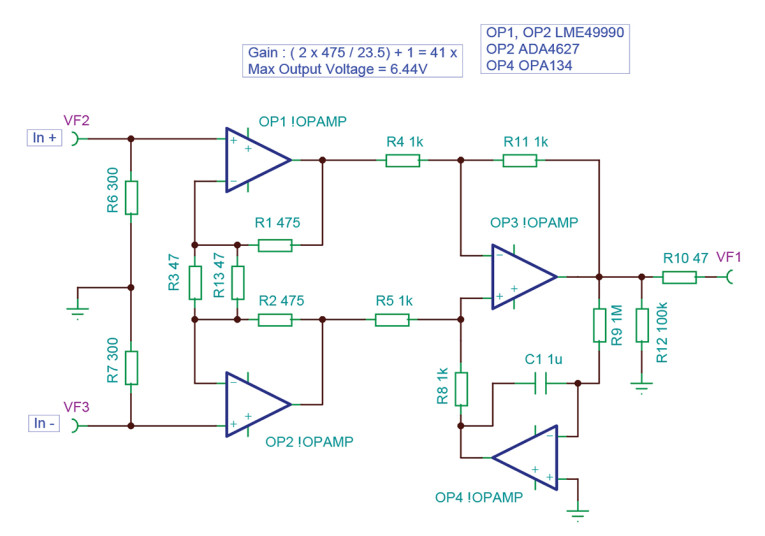
Actually, a DC servo in an INA can potentially sound better because the output stage is lifted from ground and connected to a virtual ground provided by the servo output. In case you have some “dirt“ on the ground because of a non-optimal layout, this little add-on can avoid ground contamination entering the differential output stage.
JD: How about matching all those resistors in the INA circuit? Is that important for phono applications?
JG: Yes, it is important, just as in other precision applications. For best common-mode rejection, it is necessary that all resistors are well matched. 0.1% is fine I think for audio. In critical medical and aerospace applications 0.01% is not uncommon and resistors need to have a low and similar Tc (temperature coefficient).
The same matching requirement is true for the differential RIAA network I use as well so frequency selective components like caps have to be matched for best results. I will talk about that later when we discuss the differential RIAA equalization stage. The INA by nature has a balanced input so that means that it has 6dB more gain than a unbalanced solution but also has more noise due to the two op-amps in series plus the Johnson noise of R2. In total that amounts to a 3dB noise penalty compared to a single-ended solution with the same amount of active input devices and the feedback resistor.
For a more in-depth analysis of noise in INAs and other topologies read Burkhart Vogel’s book The Sound of Silence [3]. But fear not, we will talk about a way to minimize noise close to the theoretical minimum later, remind me if I forget! In fact, the circuit simulates in Microcap to have -76dB of noise unweighted referenced to 1mV and that translates into better than 80dB weighted. No vinyl source material I know of has that kind of dynamic range. Burkhart Vogel’s book also discusses dynamic range. He makes a convincing case that maximum dynamic range on a vinyl record cut with DMM is around 72dB. A conventional lacquer cut vinyl record has a noise floor that is 6dB to 8dB worse.
JD: In practice, everything around the cartridge and (op)amp has resistance and thus contributes noise, right?
JG: Yes, the Johnson noise from the impedance of the cartridge and the wires say 5Ω has to be added and even a theoretical noiseless MC input cannot be better than 0.2nV/rtHz with a 5Ω cartridge connected. So, in practice we have the following situation: The lowest noise phono stages I know of are the Synaestesia HP3, HP4, HP5 [4] and my Ultra Low Noise Rosi plus the Ultra Low Noise High Z MPP. I do not know any commercial stage on the market that betters this. Jürgen Ultee’s “Grail” is in the same ballpark, so is John Curl’s Orion with 0.4nVrtHz.
Actually, going lower than 0.3nVrtHz is nearly impossible without substantial cooling due to the laws of thermo-dynamics no matter how many devices you parallel, not to mention layout and oscillation problems. So, the HP3 would be 0.3nV/rtHz plus 0.2nV/rtHz from the cartridge amounting to 0.5nV/rtHz and the Discrete INA FPS I will discuss later is 0.5nV/rtHz plus 0.2nV/rtHz amounting to 0.7nV/rtHz, shrinking the theoretical 4.5dB advantage down to less than 2dB in a practical setting. I can live with that considering that the FPS has the advantage of balanced operation, namely superb rejection of external noise fields like hum from transformers and motors. So, the FPS holds the low noise record for balanced active stages as far as I know. aX
This article was originally published in audioXpress, September 2024
In Part 2, Joachim Gerhard will further develop his design ideas with a discrete instrumentation amplifier topology.
References
[1] P. L. Rossiter, “A Head Amp for Very Low Impedance Moving Coil Cartridges,” audioXpress, September 2006.
[2] A Designers Guide to Instrumentation Amplifiers, 3rd Edition, Analog Devices, www.analog.com/media/en/training-seminars/design-handbooks/designers-guide-instrument-amps-complete.pdf.
[3] B. Vogel, The Sound of Silence: Lowest-Noise RIAA Phono-Amps: Designer’s Guide, ٢nd Edition, ISBN 978-3642197734, Springer Verlag, Germany.
[4] “Low Noise Designs: Low Noise Schematics,” DIY Audio,
www.synaesthesia.ca/LNschematics.html

Flexible Phono Stage (FPS) by Joachim Gerhard
The name FPS comes from the fact that you can arrange the input in two different ways: High Z and Low Z. The High Z version has the advantage of DC coupling and loading resistor types and values can be changed at will to optimize coupling to the cartridge. Low values usually sound more robust and high values sound airier. I use 2× 300Ω on my Lyra Titan I for example. Higher value loading gave a sound that I found too bright, but your system and taste may differ.
The Low Z version needs AC coupling. I use modern shunted electrolytic caps with polymer dielectric here. The Nichicon LG series I use has a 2200µF cap that can stand more then 6A of ripple current and has an ERS at 100kHz of only 8mΩ. It comes in a very small package, so a compact layout is possible. Its disadvantage is a high leakage current but, in my design, this current cancels in the cartridge because the current has opposite phase.
Actually, I could not measure any DC at the input with the meters I had available. Bias voltage across them is small and I use 5 plus 5 in parallel so distortion down to low frequencies should be small. As shown by Douglas Self and others, bias voltage raises distortion in electrolytics. A general rule is that the lower the signal voltage across electrolytics, the lower the distortion they cause.
Another advantage of the Low Z version is that the sources of the FETs are driven, so the nonlinear input capacitance of the FETs, which is not in the feedback loop, is out of the equation. Theoretically, the Low Z version is faster and has less distortion in the treble. In terms of noise the Low Z version has the edge. Impedance of the cartridge is parallel to the feedback resistor R2 in this case so that this resistor actually lowers the noise of the cartridge. For example, a feedback resistor of 5Ω plus the 5Ω of the cartridge would make the noise impedance 2.5Ω. Compare that with the 7.5Ω of the High Z version. If we would raise the feedback resistor to 10Ω the noise impedance would still be lower than the High Z case and the resistors would provide a measure of source degeneration that would improve linearity of the input stage. An endless game of permutations. Sound-wise I heard the same differences I had observed with my bipolar designs. The High Z version has very elegant tonality with some measure of warmth and the Low Z version has tremendous bass precision with a lot of spectacular raw dynamics. It’s up to you.
Component Selection
Regarding the chosen design, you have some leeway in swapping components. You can use BC550/BC560, 2SA970/2SC2240, or 2SA1015/2SC1815 BJTs to replace the 2N4401 and 2N4403 but check for different pinouts! An LME49710, OP27, OPA227, OPA134, or OPA1641 can substitute for the old standby NE5534. As mentioned, resistors should be 0.1% tolerance or better, metal film, low noise, and low temperature coefficient of resistance; values down to 5ppm tempco are readily available.
For electrolytics I had good results with Panasonic FM or similar for bypass, Nichicon LG for coupling, but more modern parts may be available at this time. I used Wima MKT, Epcos MKT, Rifa SRM and the like for bypass purposes. Finally, use 1% tolerance RIAA caps, matched between the positive and negative chain, ideally to 0.1%. Recommended types are LCR Styroflex and Roederstein MKP1832, 1% Silver Mica. aX


