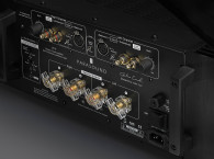
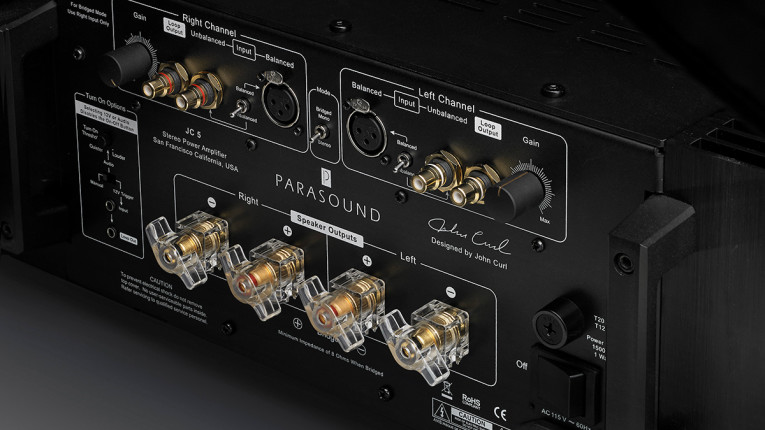
The back panel is nicely laid out, and the I/O connections are clearly marked and easy to use. I also appreciate the input gain controls, which makes life easier and safer for those of us who are connecting and disconnecting upstream equipment and don’t want to accidentally fry speakers—a real concern at the power levels on tap here. It’s also useful for gain adjustment in multi-amped systems. One small note: Make sure that if you drive this amp with both balanced and unbalanced sources, you remember to use the toggle selector switches on the back to choose which one you’re using. Otherwise, you can have some very puzzling losses of gain... not that I’d ever be forgetful and do that, of course.
The topology of this amp will come as no surprise to anyone familiar with John Curl’s designs. His basic philosophy is wide bandwidth and low distortion before applying feedback, and he tries to minimize feedback as well. He tends to use FETs liberally in his driver circuits, runs his output stage idle currents a bit rich, and uses complementary circuitry wherever possible.
For the Parasound Halo JC 5, the inputs are buffered by discrete constant current source (CCS) loaded junction-gate field-effect transistor (JFET) source followers, which are direct coupled to a fully complementary bridged JFET differential amplifier. The JFETs are cascoded with bipolar transistors to decrease Miller effect and linearize the input stage by holding the drain-to-source voltage nearly constant. The differential signal at the cascode collectors is converted to single-ended and amplified by a bipolar Vas stage, again fully complementary, with their collectors connected together via a bias spreader (constant voltage) circuit. Complementary MOSFET source followers then drive the output stage, which consists of six paralleled NPN-PNP pairs, for a total of 12 output devices per channel. Output offset is corrected via an op-amp configured as an inverting integrator to avoid the usual large electrolytic capacitor in the feedback loop and any input capacitors.
After my exertions getting the amp unpacked and sited, I first gave it a quick listen, substituting it for the nCore amps in the NAD M10 that drive the midrange-tweeter section of my speakers; once the levels were adjusted, the JC 5 sounded just as clean and transparent as the nCore. The JC 5’s extra power made itself known on a few recordings at brisk sound pressure levels, where I managed to clip the NAD, but the JC 5 played flawlessly. Using a Purifi Eigentakt amplifier in place of the NAD amp, I was also unable to hear any significant difference. Satisfied that it is audibly as clean and transparent as a good amplifier should be, it was time to take it out of my system and grunt it to the lab benchtop.
On the Bench
As usual, my test setup includes an Audio Precision (AP) APx525 audio analyzer and various home-built dummy loads — I leveled up the dummy loads for this review to accommodate the JC 5’s rated power. I did miss one thing, though, which I’ll talk about shortly. For ultra-low distortion measurement, I also use a Vicnic 1kHz oscillator as a source, and a passive twin-T notch filter between the DUT output and the AP’s input.
The JC 5 ran cooler than I expected, about 40°C on the heatsinks after a long idle or low power use, and climbing to about 53°C after a few hours of pushing it hard. The FTC preconditioning (one-third power sine wave into an 8R load for 1 hour) got the heatsink temperature up to almost 60°C, which is pretty hot but not enough to leave a mark. Because of the thermal mass of the metal used in construction, the front panel barely warmed.
I began with some baseline measurements, starting with voltage gain at zero attenuation, which was 28.8dB and 28.9dB from the left and right channel, respectively, in balanced mode. Unbalanced gain was barely different. Input impedance is specified at 66kΩ for balanced and 33kΩ for unbalanced, and measured almost exactly that.
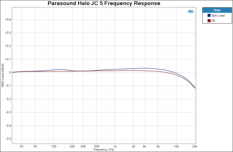
Output impedance was below my reliable lower test limit (10mΩ) across the entire audio band. This implies that the frequency response will not be altered much with real-world speaker loads having large impedance variations with frequency. This is evident in the frequency response measurements (Figure 1). The change from an 8R resistive load to a loudspeaker only perturbed the response by 0.02dB. The response starts rolling off at the top of the audio band, down 0.1dB at 20kHz, which suggests sensible filtering.
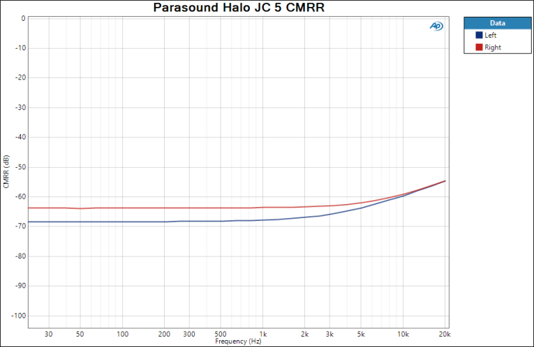
One of the key advantages to balanced connections is rejection of common-mode noise. This, of course, is only the case if the source is truly balanced (i.e., has identical impedances on each leg) and the receiver has a high common mode rejection (CMR). Although CMR is generally given as a single number, typically at 60Hz or 120Hz, it will usually vary with frequency. Since common-mode noise can have many sources other than mains pickup, a well-designed balanced input stage will have high CMR across the entire audible range. Figure 2 shows the JC 5’s response (input-referred) to a common-mode input as a function of frequency; at mains frequencies, the CMR is 68dB and 64dB for the left and right channel, respectively, declining slightly to 55dB at 20kHz. This is very good noise rejection performance.
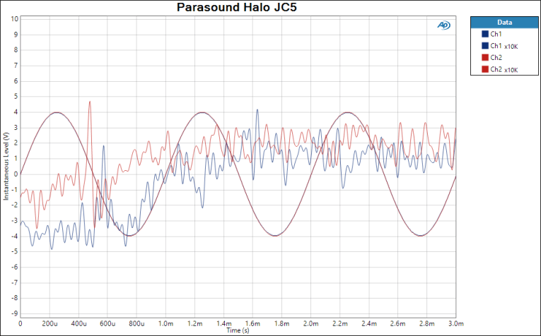
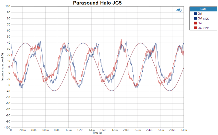
It’s often interesting to look at distortion and noise residuals, especially at low power where artifacts like crossover distortion can become audible issues and where an amplifier spends most of its time when playing most music. Figure 3a shows the JC 5 output when playing a 2.83V sine wave at 1kHz into an 8R load (1W). Superimposed is the distortion residual magnified by 10,000 (80dB); the residual is almost entirely dominated by noise, with no visible signs of discontinuity at the zero crossing. Increasing the output voltage to 28.3V (100W) gives the waveform and residual shown in Figure 3b. It is dominated by the second harmonic at a very low level (0.03%). Clearly, the bias control of this amp is quite effective.

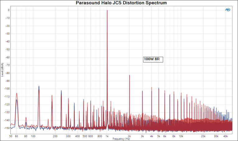
The spectrum of a 1kHz/1W/8R sine wave is shown in Figure 4 for both balanced and unbalanced inputs. The predominant noise component is from the power supply at 120Hz, with a level of -88dB in both modes. To put that in perspective, if you have extremely sensitive speakers (e.g., horns) and you put your ear right up to them, you may be able to barely detect it — but if you have speakers that sensitive, you’re unlikely to be pairing them with a 400W amplifier! Likewise, distortion is essentially identical in both modes and reasonably low, with the second harmonic being predominant at -100dB. Cranking it up to 100W gives the spectrum in Figure 5, with the second harmonic increasing to -82dB.
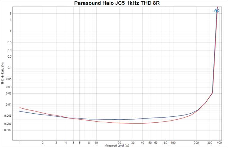
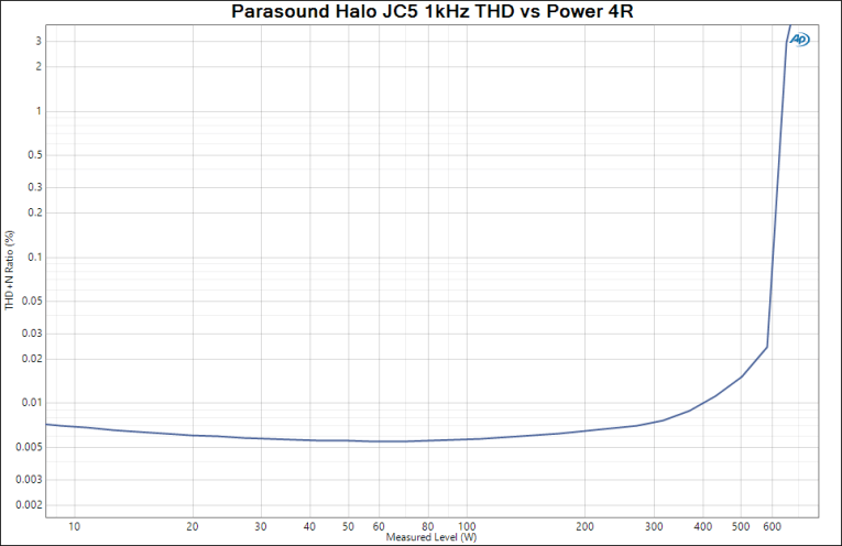
Next, I attempted to measure the THD vs. power level at 1kHz; using an 8R load, I obtained the curve shown in Figure 6. This was a bit surprising, with the amp showing its overload knee at 320W, with a 1% THD reached by 350W, a good deal of power but short of the specified 400W. With the load reduced to 4R, the amp comfortably met its 600W specification (Figure 7). On investigation, I discovered that despite being on a separate circuit for my lab/listening room, the JC 5 drew enough current to cause the line voltage to sag from a nominal 120V to 112V. This was the limiting factor for the 8R continuous measurement, and applying a correction indicated that the amp would make slightly over 400W with a stiffer electrical supply. Moral: If you’re running equipment with this kind of power capability, you may want to put in a dedicated 25A power circuit!
My house wiring problem notwithstanding, I also tested the dynamic power using a series of tone-bursts, which is a short enough stimulus to avoid sag in the supply voltages both from the mains and from the amplifier power supply. With an 8R load, peak power was about 530W, which is 1.25dB of headroom above the rated continuous power.
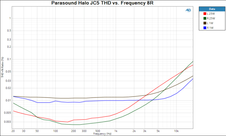
I then looked at the dependence of THD+N on frequency at low (1W) and moderate (25W) power levels, with the results shown in Figure 8. At low power, the noise part predominated up to about 5kHz, at which point the distortion starts to rise, reflecting the inevitable drop in open-loop gain. At 25W, the noise floor drops below the distortion at mid-band, with the same rise in distortion in the top two octaves. Nonetheless, the distortion is reasonably low, and certainly well below any auditory threshold.

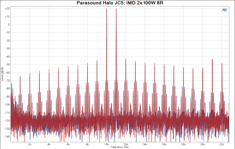
Moving up the ladder of signal complexity, the two tone (10/11kHz) intermodulation distortion spectrum driving an 8R load, with each tone set at 2.83VRMS (0dB on this scale), is shown in Figure 9. The first-order product (1kHz) is under -93dB from the reference level, with sidebands at -90dB. The largest distortion components were actually the second harmonics of the test tones at roughly -70dB (0.03%). Stepping on the gas, with each tone now at 100W (+20dB ref 2.83V), which is a rather punishing signal, the largest distortion component in the graph of Figure 10 is still -65dB below 100W (0.06%). While this isn’t a state-of-the-art number, it’s still far below any audible threshold.
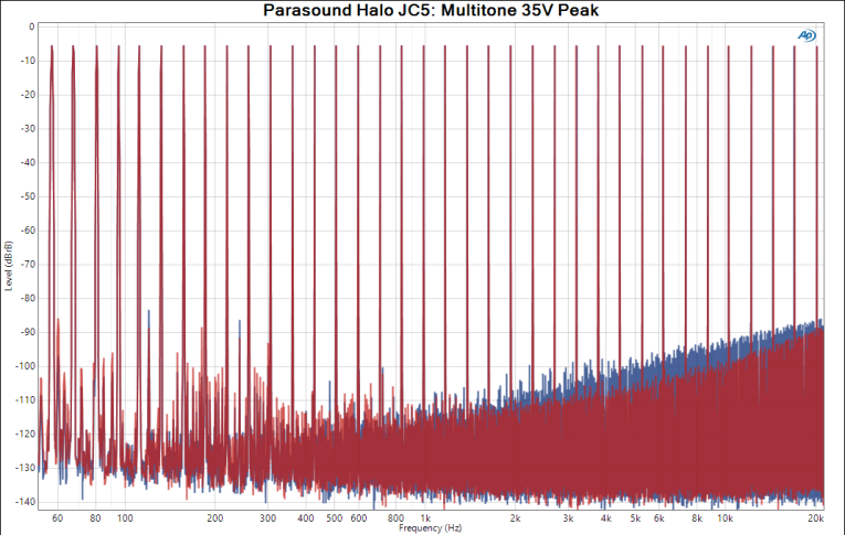
And finally, the multitone spectrum at 35V peak output into a 4R load is shown in Figure 11. As expected, at lower frequencies, the main offender is mains and power supply frequencies (multiples of 60Hz). At higher frequencies, things get a bit messier due to reduced feedback, but the level of distortion is still quite low and unlikely to be of sonic consequence.
To Summarize
The Parasound Halo JC 5 is a real powerhouse. The measurements fall short of state of the art, but are still orders of magnitude below audibility, and used in my system, I could not detect a sonic difference between the JC 5 and the two top quality Class D amps that I usually use. The I/O options and look and feel of the controls are superb. In balanced mode, the suppression of common mode noise is surprisingly good. This is a very well-engineered “classic” linear amplifier. aX
This article was originally published in audioXpress, September 2021.
Click here for the first part of this article, the subjective review by Oliver Masciarotte.
 About the Author
Stuart Yaniger has been designing and building audio equipment for nearly half a century, and currently runs a technology consulting agency in western New York. His professional research interests have spanned theoretical physics, electronics, chemistry, spectroscopy, aerospace, biology, and sensory science. One day, he will figure out what he would like to be when he grows up.