Production instruments are generally less flexible, but easy to program to allow production staff to perform repetitive tasks such as quality control checks rapidly, consistently, and without having to delve into the engineering. All of this comes at a price, of course, but traceability and the ability to automate are vital for manufacturing.
Small shops and home users have been blessed by the proliferation of high-quality computer sound cards or analog interfaces, depending on whether the target audience is musicians or audio developers, and incredibly versatile measurement software packages. With suitable external electronics (signal conditioners, microphone preamps, power amplifiers, test resistors, and more), a small lab can perform just about any imaginable audio measurement. And do it cheaply — the cost for an excellent sound card plus signal conditioner (the Didden Autoranger II, for example) plus software comes in well under $1000. For a few hundred dollars more you can add a calibrated mic and a small amp. With this equipment in hand, a user can achieve measurements at the same level as the professional gear, the tradeoff being time for integration, setup, calibration, and inevitably troubleshooting. And for many, that’s a bridge too far.
Intermediate solutions have appeared on the market, such as Prism Sounds’ dScope series — now Spectral Measurement — coming in at between one-third and one-half the cost of gear from companies such as Audio Precision. These systems integrate software and hardware in the same seamless manner as the higher-priced gear, albeit with slightly lower (though still excellent) performance.
Still, the small lab and home testing niche is one with limited options, so Echo Test + Measurement has stepped in with its AIO Test System.
The Company
Echo Test + Measurement is the latest iteration of a Santa Barbara, CA-based company originally called Street Electronics, and later in the 1990s known as Echo Digital Audio. Its product lines have changed with the times — my first exposure to them was perhaps 15 years ago when its specialty was audio recording interfaces and external sound cards. I had a two-channel version of its AudioFire line, which I used as both a recording/playback interface and as part of a sound-card-based audio measurement setup with an older Macintosh computer.
The only problem was something that Echo couldn’t control — the Firewire interface (equivalent to IEEE-1394) was standard for Apple products, until it wasn’t. Apple changed over to a USB interface, and Firewire receded into history, along with a lot of now-obsolete development work. And the AudioFire went back into a box and is still collecting dust in my garage storage, a pity since its performance was excellent. I tried using an IEEE-1394 adapter to my Windows laptop, but that was clumsy and unreliable compared to the Firewire connection with my old Mac.
Echo made a lot of other great external cards (and at least one internal PCI card), but that’s now a market with a lot of players and commoditization. However, the technologies integral to Echo’s core competencies could also be applied to customizable commercial audio production test gear, and that brings us to the AIO Audio Test System.
The Product
Echo realized that test equipment for manufacturing lines that can be integrated into automated test systems was a natural use for its technology, and to customize it for wide use, its approach resembles mainframe oscilloscopes with various plug-ins. After making a large quantity of these systems for automated production line testing, Echo decided to try to sell it in the home lab and small commercial lab market, where the economies of scale brought the price down to a very affordable level.
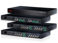
The resulting AIO system is an enclosure with power supplies and support circuitry to which two modules may be added at the customer’s request. The enclosure is a slim stackable unit with a pilot light on the front panel (Photo 1) and both power and I/O on the rear panel (Photo 2). The “mainframe” has the power and the USB interface, then space for two modules chosen by the user to customize the test system. Module options are:


AIO-A (Acoustic): The Acoustic module has four inputs that can be used for ICP/CCP microphone or as line inputs, and two amplifier outputs rated at 10W each into 8Ω. This module is suitable for basic speaker testing (frequency response, polar pattern).
AIO-C (Combo): This module is designed for logging environmental variables (temperature, pressure, humidity) rather than audio measurement.
AIO-H (Headphone): The Headphone module has two ICP/CCP mic inputs, suitable for embedded mics in artificial heads. There are two audio outputs with 3V and 125mA maximums, more than enough for the majority of headphones and headphone transducers. One is a conventional voltage output and the other has a 0R1 series resistor to generate a voltage proportional to the transducer current. The voltage developed across that resistor is then monitored by an internal floating differential amp. Additionally, the outputs are equipped with remote sensing (four wire or Kelvin connection) to allow accurate impedance measurement without having the impedance of cables contaminate the measurement.
AIO-L (Line): This module provides four single-ended line or ICP/CCP mic inputs with a maximum input range of 6.2V at an x1 gain setting, and two balanced floating outputs with a 2.0VRMS maximum output into a 600R load.
AIO-S (Speaker): The Speaker module is similar to the Acoustic module in that it has two 10W amplifiers built in, but has two inputs for line or ICP/CCP, and one of the two amp outputs has a 0R1 series resistor similar to the Headphone module to measure the speaker current. Like the Headphone module, the amp with a series resistor also has a four-wire connection for eliminating the effect of speaker cables in impedance measurement.
AIO-T (TDM): The TDM is a digital module useful for monitoring data streams in I2S and DSP format. It offers eight channels, 192kHz sampling, and 24-bit or 32-bit operation.
Note that, unlike oscilloscope mainframes and plug-ins, the modules must be installed and configured at the factory and are not user-changeable. An AIO Test System with one module sells for $2750. Adding a second module bumps the price to $3250.
The microphone inputs are all ICP/CCP, that is, a single-ended constant current system with BNC connectors. I have written about this method previously (see Resources). It is common for industrial measurement, but less common in home and small commercial labs where balanced phantom power mics tend to predominate.
A major advantage of ICP/CCP mic systems is the ability of the interface to read calibration data directly from the mic via the Transducer Electronic Data Sheet (TEDS) or IEEE 1451 protocol. This can be a real timesaver compared to manual entry of sensitivities, especially when mics are being moved around between inputs. And if you have a lot of test mics around, without TEDS you also have the fun of finding the calibration sheets to get the numbers from… because the datasheet is built into the mic, TEDS is a lifesaver for absent-minded sorts like me.
Rather than use standard XLR or other common connectors in home or pro audio, Echo chose to use pluggable terminal blocks, which accommodate stripped wire ends that are screwed into a connector, which in turn is then snapped into a receptacle on the AIO plug-in. This requires the user to make adapter fittings for any standard connection, but has the advantage of being agnostic as to the type of connectors in DUTs. It also simplifies the mechanics of making connections because the user doesn’t have to wangle screwdrivers into inconvenient locations, the connector block comes to him or her.
One excellent feature missing in nearly every other test system: the line inputs have an impedance of 1M. This means not only a reduced tendency to load down circuits being measured, but also that scope probes can be used. I hooked a standard 10× probe to one of the inputs and confirmed that it passed square waves at the correct voltage ratio.
The AIO in Use
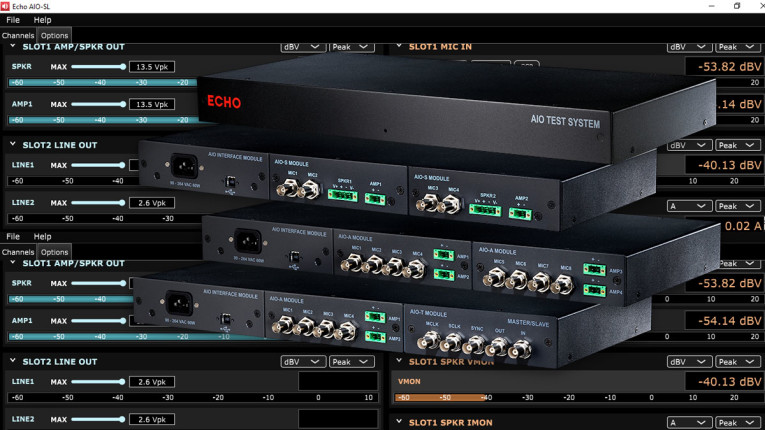
Because of a particular set of measurements I wanted to do, the plug-in options I chose were the AIO-S and AIO-L. The AIO appears as a sound card when connected to your computer’s USB port. The driver installation went smoothly, and when the AIO was connected, the control panel popped up (Figure 1). The control panel automatically populates according to the installed plug-ins. It allows the user to select sample rates, gains for each input (×1, ×10, ×100), turn on ICP/CCP power when an input is used for a mic rather than line, and set maximum levels for each output (this doesn’t change the gain, so be aware that the output will hard limit at that maximum level). It should be noted that gain selection is manual—the AIO does not autorange, so the user needs to be aware of this when measuring some high dynamic range phenomena.

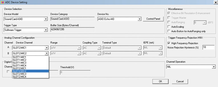
Additionally, the control panel enables the user to monitor input and output levels during test setup, in lieu of the measurement software package chosen. Speaking of which, during my evaluation, I used REW, ARTA, and Virtins Multi Instrument and it interfaced flawlessly with each of them, with their respective menus allowing the choice of any of the I/O ports on the AIO modules; Figure 2 shows how the choices appear in the Virtins Multi Instrument device menu. According to Echo, the AIO also works with Audio Precision’s APx Flex measurement software. I didn’t have that on hand, but since the AIO appears as an ASIO device, I was able to simulate the last by running the APx500 software with the APx525 on my bench acting as a very expensive dongle, and choosing the AIO as either the input or output ASO device—after a few initial crashes and power down/restart, everything thereafter worked perfectly.
The control panel software can be addressed by command line or API if the user wants to automate a process. I note that the Virtins Multi Instrument software I used for many of my measurements can be programmed to access the control panel, run a test sequence, then output a QC check “yea or nay.” So if, like me, you are averse to coding, automation can be easily customized with standard software.
My first quick check was configuring the Line and Acoustic modules’ inputs as line input, then running a 1.000VRMS 1kHz sine wave from the APx525 into each of them. The voltage reading shown on the control panel was 1V for all inputs. Likewise, a 100mV signal at a 10× gain and a 10mV signal at 100× gain gave output readings of 1V, a tribute to the accuracy of calibration.
Since I didn’t have an ICP/CCP mic, Echo was kind enough to loan me one, a GRAS 46AE. I used TEDS to retrieve the mic data (Figure 3), then I used a GRAS 42AB calibrator to check the sensitivity spec. This calibrator puts out 114dBSPL, so the mic output should be 10 times higher than the standard 1Pa/94dBSPL spec of 42.2mV/Pa. And at the indicated 0.424V, it certainly looks like all the calibrations line up very well.

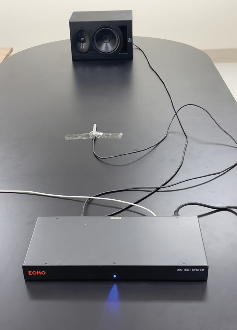
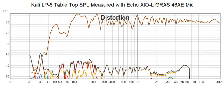
With the AIO verified to be running properly, I pressed it into service doing some acoustic and electroacoustic measurements. First I used the L module to measure frequency response and distortion of some active speakers I was modifying for use as desktop speakers (Photo 3). The line output of the L module was connected to the speakers, and the GRAS mic that Echo sent me was connected to the ICP/CCP inputs. The TEDS data was acquired, the calibration set, and then I used REW to get the acoustic data using log-frequency sweep (Farina chirp). Here’s where the Echo was a major improvement over my usual APx525/1701 test system—no fan! Normally, I have to move the AP equipment and its associated lab computer to another room and run very long cables in order not to contaminate the measurement with the very significant fan noise from the two AP boxes. The Echo has no fan, is dead silent, and worked great just a few feet from the speaker.
Using the Echo, I obtained the graph shown in Figure 4, which looks pretty much like the same data I have been getting with the AP boxes, but in a fraction of the time since I didn’t have to move equipment and run cables.
Likewise, I have been working on a project to map out actual voltage and current requirements for passive loudspeakers using real-world signals so that amplifiers can be designed to meet all use requirements for a particular application. The APx units are excellent for this since there’s a current monitor built into the APx1701 acoustic interface, and in theory, you can acquire the voltage and current data separately, then graph them on an
I vs. V Cartesian plot.
Unfortunately, the acquisition and storage of the data in such a way that the I and V can be lined up synchronously and at high resolution is a bit obscure (you’d think the Scope function would work, but it doesn’t), and there is no provision in the APx software to create such a plot. Eventually, I found a workaround for the first issue, but the second requires all the data to be exported to Excel or similar package, then the graph created using the external software. I will attest that having Excel deal with multimillion cell spreadsheets causes spectacular slowing of my computer! Each plot took nearly an hour to acquire, process, and graph.
By contrast, with the Echo AIO-S module and Virtins Multi Instrument software, I had the measurement up, running, and graphing in minutes. Figure 5 and Figure 6 show I vs. V plots for a two-way passive speaker driven by the AIO-S’s amplifiers at reasonably high volumes using two different sets of source material: pink noise and a 40 frequency multitone signal.
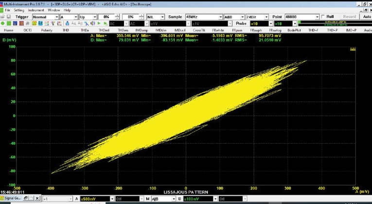

I’ll be systematizing these data (and data acquired with music and speech signals) in a future article, but the point I wanted to make here is that the integration of the Echo AIO-S made this a fast and easy measurement instead of a struggle.
Echo AIO Test Measurements
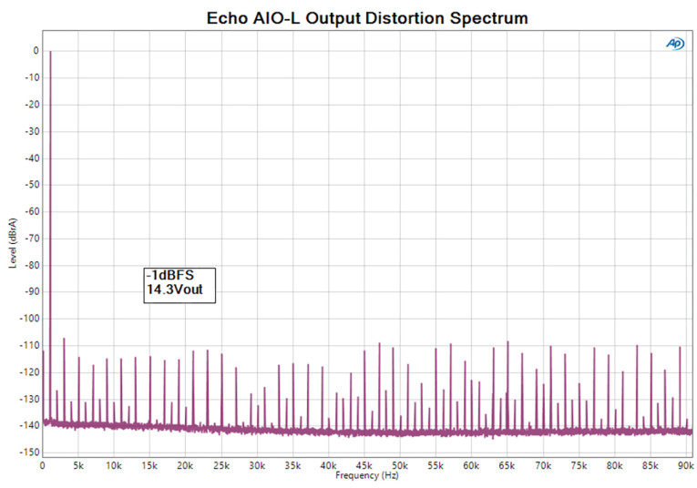
I checked several aspects of the AIO’s performance using an Audio Precision APx525. First, I attached 8R dummy loads to the Speaker module’s power amplifiers. With no signal, the noise spectrum is shown in Figure 7. The ultrasonic and carrier noise is exceptionally low, with the worst component being under 3mV at about 300kHz. Next, I looked at the distortion performance of each of the modules. Starting with the AIO-L, I first looked at the output distortion by addressing the input via ASIO, setting the level to -1dBFS and measuring the output in balanced mode. At that level, the output was 14.3V, so the full-scale voltage is about 16V. The distortion spectrum of a 1kHz sine wave is shown in Figure 8. The third harmonic is strongest at -108dB with respect to the fundamental. There’s a lot of higher-order harmonics visible, albeit at extremely low levels. Raising the frequency to 10kHz at the same output level, I measured the distortion spectrum shown in Figure 9. The third harmonic has risen to about -103dB, and within the Shannon-Nyquist frequency limit, higher-order harmonics make themselves known. These are good results and good enough for most applications, but not at the level of current state-of-the-art electronics.


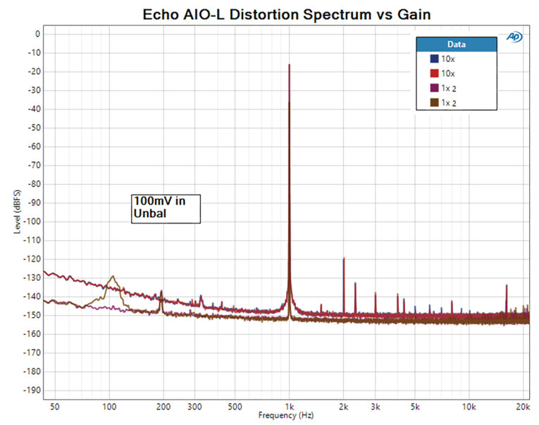
The input distortion results for a 100mV sine wave are shown in Figure 10. These were obtained by feeding a single-ended signal into the line inputs, then addressing the AIO output via ASIO. At a ×1 gain setting, absolutely no harmonics were visible. When the gain was increased to ×10, harmonics popped up out of the noise floor, with the second harmonic predominating at -105dB. I used a log frequency plot here to show that there’s a noise rise at lower frequencies, and it scales with gain, suggesting its origin is the input stage.
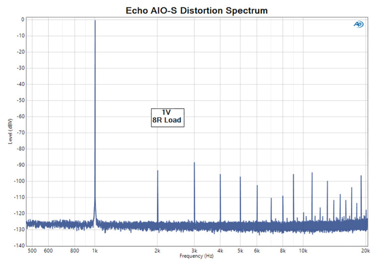
I attached 8R dummy loads to the outputs of the power amplifiers in the S module, and applied a 1kHz sine wave. At 1V out, the distortion spectrum looked like Figure 11, with third harmonic predominant at -88dB. I increased the output to 2.83V (1W), then swept the frequency from 20Hz to 20kHz, obtaining the lower curve shown in Figure 12; the distortion stays at about 0.01%, but then starts rising at 1kHz.
The drop after 12kHz suggested that the anti-aliasing filters were suppressing the harmonics, so I reset the sample rate to 192kHz to capture the distortion at the top of the audio band. This is shown in the upper curve of Figure 12. The increased distortion below 1kHz at this sample rate is due to capturing more ultrasonic noise and won’t impact normal loudspeaker measurements, but the high distortion (up to 3% at 20kHz) is due to the amps. Again, depending on the measurement you’re trying to perform, this may or may not be a problem, but if I were (for example) measuring distortion performance of tweeters, I’d want to use the L module and an external amplifier.

Complaints, Cavils, and Squawks
Every silver lining has a cloud, and the AIO is no exception. Most of the issues that bothered me were a direct result of the AIO being originally designed for production lines rather than the test bench. For example, the connectors and power are all on the back of the unit rather than the front. This made attaching and removing cables — something rarely done in a manufacturing environment but constantly done in a home or small lab, more of a hassle than having all the connectors in front and visible. If you’re using it in a more permanent bench setup (e.g., for QC tests), this is a non-issue.
And speaking of connectors, the terminal blocks are rather straightforward for adding whatever connectors are suitable. However, it is a bit inconvenient to make up the plugs and jacks, and they make a mess on the bench when all the I/O ports are in use. It would be nice to have a few standard connection options (e.g., combo XLR/TRS and phono plugs built into the unit), or offer a patch panel as a plug-in option.
Although ICP/CCP mics are common in large labs and commercial facilities, I think my exclusive use of balanced phantom power mics might be more common for small labs. It would be nice to have that option; because ICP/CCP is the only mic input option, I borrowed a mic from Echo for this evaluation. (It was an extremely nice one, thanks, guys!)
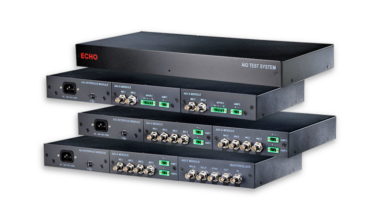
The Echo AIO has some great things going for it — compact integrated design, physically quiet (no fan noise!), extremely easy to configure, and seamless compatibility with every piece of measurement software I threw its way. Measurements that were massively painful using other test systems were trivially done with the AIO. The ability to use standard scope probes is also a blessing. For a small manufacturer, it would be a great addition to outgoing QC and characterization.
The shortcomings about which I previously complained are a legacy of the original design intent and are all relatively easy to deal with. The AIO with the modules I ordered does not have state-of-the art distortion performance, but it’s good enough for most applications.
Where it really showed its stuff was in acoustic measurement, where the lack of fan noise made setup and cabling much easier, and the versatility enabled novel measurements that I could not do easily with APx or CLIO. At its relatively low price and with its ability to be customized, small labs and manufacturers will find great value in the Echo AIO. aX
Resources
J. Martins, “Echo Test Measurement - Specifically Made for Audio Testing!” audioXpress, March 2022
S. Yaniger, “Fresh From the Bench: Measurement Microphones from PCB PiezotronicsFresh From the Bench: Measurement Microphones from PCB Piezotronics,” audioXpress, December 2016.
S. Yaniger, “The Virtins Multi-Instrument Software,” audioXpress, March 2016,
S. Yaniger, “The Lab Bench of 2021: Virtins Multi Instrument Measurement Software,” audioXpress, March 2021, https://audioxpress.com/article/the-lab-bench-of-2021-virtins-multi-instrument-measurement-software
This article was originally published in audioXpress, March 2023


