This year, the Audio & Loudspeaker Technologies International (ALTI) Association joined forces with the Audio Product Development Alliance (APDA) to reinforce the educational aspects of the ALTI Expo & Conference. With a very strong schedule of sessions, presentations, and workshops, the APDA-ALTI Education Symposium 2023 covered Sourcing and Supply Chain topics on the first day, followed by a full day focused on the Modeling and Measurement experience, and extending into an education-only third day centered around Voice and DSP.
Modeling and Simulation has advanced greatly with the innovation in software tools brought to market by companies like COMSOL. Measurement systems today can and do collect vast amounts of data about product performance, quality, consistency, and more. The next frontier is bridging the gap between simulation data and measurement data.
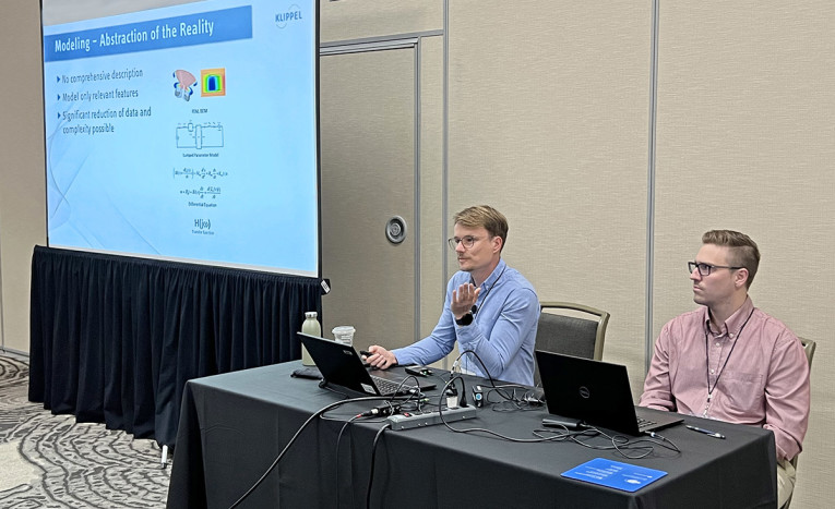
Integrated in the APDA-ALTI program, a session promoted in cooperation between COMSOL and Klippel, two leading companies from both disciplines in the audio industry, offered an historical perspective about the Integration of Simulation and Measurement Data.
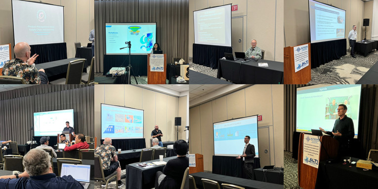
Mark Cops, an Applications Engineer with COMSOL, and Robert Werner, an Applications Engineer with Klippel, joined the effort to illustrate how to integrate loudspeaker measurements with simulation modeling. During the presentation, they discussed data management, comparison, and model updates for optimization, which is the most powerful part of the audio production simulation and production cycle.
In what is expected to be chapter one of many, Klippel demonstrated how a set of parameter measurements based on a nonlinear electro-dynamic model can fully define a linear and nonlinear lumped parameter model, with the goal of importing a table of parameters into a CAE simulation modeling software platform such as COMSOL to build a comparable simulation model for validating the model and the measurements.
The table of parameters from the Klippel measurements are applied to an equivalent lumped parameter model at the nodes in the CAD geometry, which are defined using COMSOL Multiphysics for the coupling of the electro-dynamic behavior. The parameter table is used in a COMSOL Function, which defines that lumped parameter model.
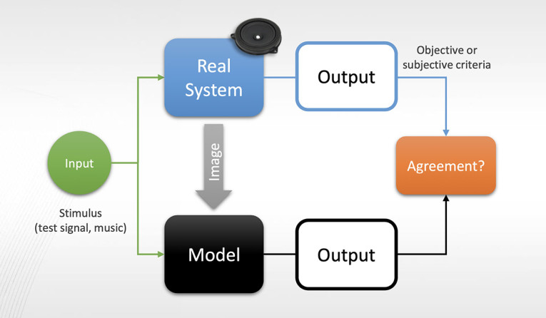
This case also represented a process that was initiated from the measurement of an existing loudspeaker design, from which the COMSOL model was generated. The reverse could also be possible. A new design generated in COMSOL using a full Multiphysics electro-magnetic model and electro-mechanical model coupled to acoustics radiation could produce the parameter table for the nonlinear electro-dynamic model for importing into Klippel. At that point a first prototype could be measured, and the results compared. Calibration of the simulation model in COMSOL could be made with updates from the Klippel measurement comparison until a validated model is available for both linear and nonlinear loudspeaker behavior.
The first procedural decision was to use either a Lumped or Distributed Model. For frequencies below the first bending mode of the loudspeaker cone, where the cone is considered a piston, the lumped model is useful. Above the first bending resonance, a distributed model is needed. For the first step in working to integrate measurement and simulation data, a lumped parameter model was used.
The linear parameter measurement provides Impedance, Displacement, Bl, Inductance, and Moving Mass. The nonlinear parameter measurement provides the Bl(x) Force Factor, Kms(x) Suspension Stiffness, and L(x,i=0) Electrical Inductance curves expressed in power series coefficients. The large signal output measurements provide the “symptoms” (i.e., the influence of nonlinear distortion). This gives us the stepped voltage response and the harmonic distortion at higher voltage.
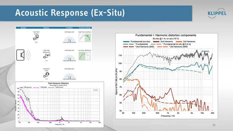
Sound pressure is measured in the near field and then corrected to an idealized standard free-field reference using Klippel’s holographic Near-Field Scanner (NFS) technology for sound field identification and direct sound separation as well as far field extrapolation. This removes the room and any baffle effects. The anechoic frequency response can be calculated as well as harmonics distortion, in what Klippel calls Acoustics Ex-Situ data (Figure 2).
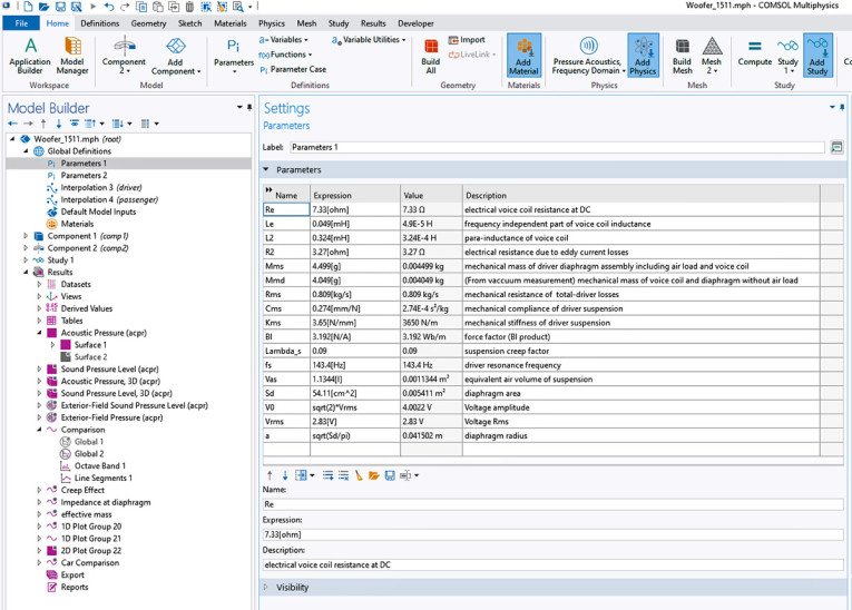
In general, the complementary process for COMSOL integrating measured data into its simulation model setup follows the same workflow that setting up a new model follows. Except that the parameters can be imported rather than manually input into the Global Definitions at the top of the COMSOL Model Builder menu (Figure 3). The workflow follows that menu from the top to the bottom: Parameter Import, Geometry Import, Physics, Mesh, Studies, and Results.
The linear and experimental data text files, along with the nonlinear data text file, are imported into COMSOL as parameters. An Analytic function is created under the Component Definitions in COMSOL for each of the nonlinear parameters, defined as a five coefficient power series (0-4) function. The geometry is imported from the DXF file from the laser scan. The 3D geometry is smooth and the 2D symmetry is used to reduce the Degrees of Freedom (DOFs) in the model, reducing solving time.
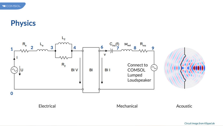
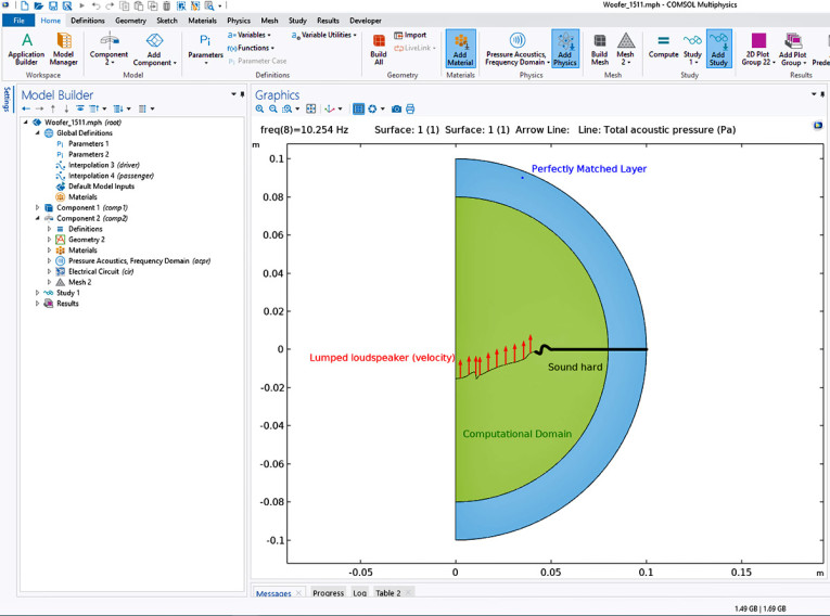
Then the physics models (Figure 1) are applied. The electric circuit interface solves a coupled system of differential equations for current through each device, and it is here that each of the nonlinear parameters are coupled. The equations are solved using Kirchoff’s conservation laws for the electrical circuit. And, then Pressure Acoustics are set up for solving the Helmholtz equation for acoustic pressure using the finite element method (Figure 4). The interior lumped loudspeaker boundary is created to fully couple the Pressure Acoustic physics to the Electrical Circuit lumped parameter model. The electrical current is passed as a velocity condition on both acoustic sides of the loudspeaker cone. Then finally the mesh is created. Studies are set up for results in the Frequency Domain, for Time Dependent solutions (harmonics), and for Eigenfrequencies.
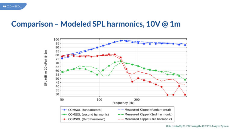
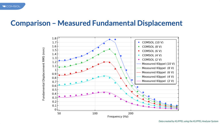
To close the loop with Klippel measurements, the results were compared (Figure 5). The difference in the third harmonic is due to the upper fundamental frequency for the COMSOL model. The mesh was refined for a fundamental upper frequency of 500Hz, and this was not defined enough for harmonics above the second. The last comparison between COMSOL and Klippel results was for the stepped voltage results for displacement (Figure 6).
What’s Next
COMSOL is looking forward to continuing the collaboration with Klippel to investigate parameter estimation for material properties of the cone for the higher frequency range. Klippel has begun the work on this front. In terms of integration for simulation and measurement data, COMSOL and Klippel went with a simple export and import for this round. Higher frequencies can follow this same process, or the reverse exchange of data from a model initiated in COMSOL can be done. Klippel has considered exporting its data as SPICE netlist, which is common for circuits. COMSOL can import this format and it would simplify creating the model. Or, COMSOL could develop an Add-in (method) specifically for reading in the Klippel .txt files for the circuit and automatically constructing the circuit interface in COMSOL. Depending on the actual need from customers who use both COMSOL and Klippel, a method could be created for them, and both companies are committed to doing so. aX
Any questions, comments or inquiries, send me an email.
This article was originally published in The Audio Voice newsletter, (#428), July 6, 2023.


