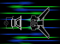
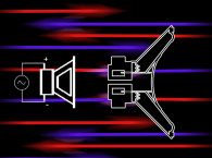
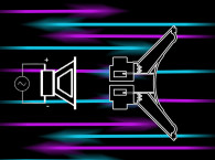
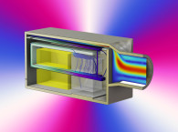
Continuing his discussion on "Back EMF Phase Relationships in Moving Coil Loudspeakers," Andy Lewis details some experiments to better understand the phenomena. Having noted that, in a loudspeaker, there are three modes of Back EMF generation - below, at, and above resonance - inductive, resistive, or capacitive, respectively - he now performs simple “thought experiments,” in order to make qualitative observations about the activity of a moving-coil driver in the region of its resonance.
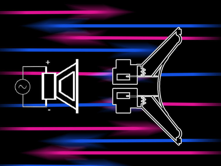
As was observed in the moving-coil loudspeaker, there are three modes of voltage generation, occurring below, above, and at the frequency of resonance. Back EMF, and resulting impedance, can be inductive, capacitive, or purely resistive. Consequently, it will take at least three separate examinations of this AC motor to describe what’s happening.
We will start at very low frequencies, where the delay in time between input current and cone position is easy to visualize. We use the word “slip” to refer to this delay in time. This concept will be explained in greater detail both in this article and in the third part of this article series.
We will proceed to higher frequencies after that. An examination of the generation of EMF at very low, DC and near-DC frequencies can provide a means to an understanding of what’s happening as frequency increases. Each illustration shows a phase delay of a specific angle. Phase delay, for each illustration, is simply described in terms of phase angle: 5°, 10°, and 14.4° of phase delay in these first illustrations, and by greater angles of delay as we proceed.
It is not necessary to reference a particular driver or frequency for this exercise, because this is only about qualitative behavior. For a slip of 5°, for example, each driver will have its own frequency. These experiments will be about what happens when a driver is driven at its own frequency for a specified angle of slip. When actual frequencies are specified in these illustrations, they pertain to the Fisher driver we have been using.
Read Part 1 of this article series
Read Part 3 of this article series
Read Part 4 of this article series
This article was originally published in audioXpress, June 2018
Read the article now available online here


