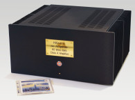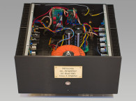

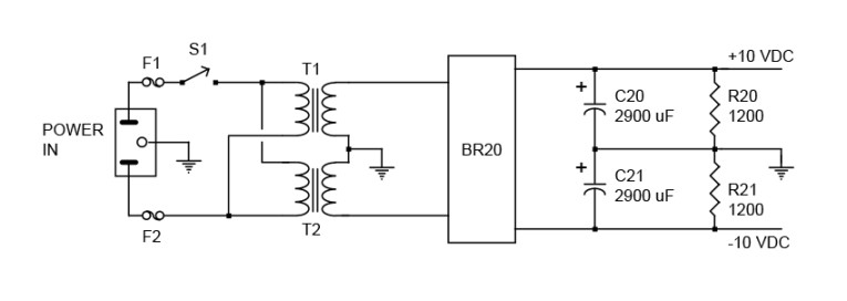
My first change was to the power supply. The useful output power is just a bit over 1W RMS into 8Ω per channel because the negative peaks start to clip at about –4.5V. So powering this amp from a ±21V DC power supply does nothing other than increase the dissipation in all the transistors. A power supply (Fig. 1) of ±10 to ±11V delivers the same output power and the amp runs much cooler. This was very important to me because I needed to rack mount it. When you have a power amp “farm,” rack mounting is the only solution. One watt RMS may not seem like much power but with a pair of high efficiency speakers (such as the TDL TSMD-2s) it fills my 17 × 28´ listening room with more sound power than is comfortable for me to listen to.
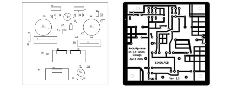
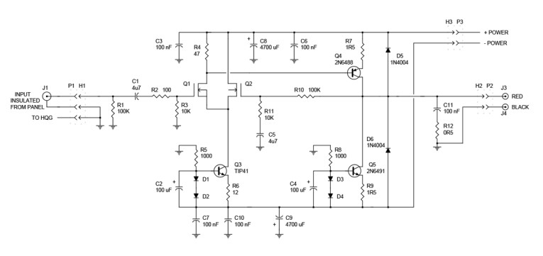
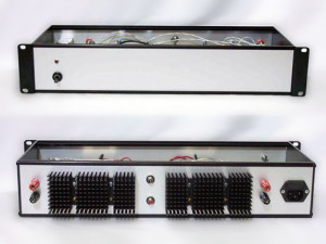
Another change was designing a circuit board (Fig. 2) with headers (and mating plugs) for making the connections on and off the board. Although the circuit is the same as Mr. Simon’s original, I redrew the circuit diagram (Fig. 3) to show the headers and the power supply changes. With Q4 and Q5 on a circuit board, there is a problem with getting the heat out. Of course, the lower supply voltages help, but Q4 and Q5 still become rather hot. Photos 3 and 4 are worth many words but some explanation is still needed. The finned radiators (Table 1) on the rear panel are very efficient so the problem is conducting the heat to them.
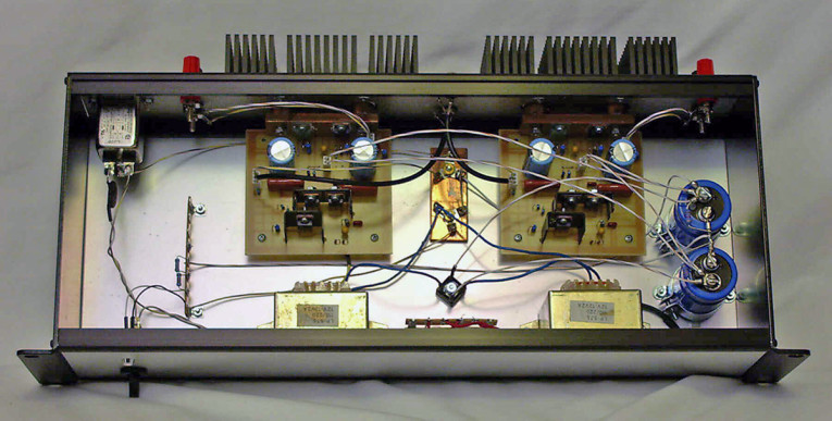
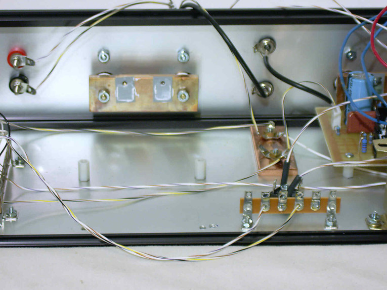
Copper (and silver) have a thermal conductivity of about unity. Aluminum (depending on the alloy) is about 0.5 and brass (again, depending on the alloy ratio) is about 0.25. So copper is the clear winner. Photo 4 shows a copper bar 1/4" thick by 1˝ wide by 3˝ long. It is tapped 4-40 in two places to mount Q4 and Q5.
What is not shown clearly in this photo are the two copper rods that connect the bar to the finned aluminum radiator. They are 5/8" in diameter and about 1/2" long. The exact length isn't critical, they just need to be the same to within a few thousandths of an inch. They are drilled with a 9/6.4" hole (at their centers) to pass a 6-32 machine screw which bolts through the finned radiator, the copper rod, and the copper bar.
Moreover, the drilled rods are soldered to the copper bar using a brass 6-32 machine screw to temporarily hold them together. I used a brass screw here because there is a slight possibility of soldering the screw to the rod or bar and brass is easier to drill out than steel. Use some paste solder flux between the rod and bar and heat with a propane torch to get a good solder joint. I punched 3/3" diameter holes in the rear panel so the copper rods would bolt directly to the radiators and I used thermal grease (the white stuff) between the ends of the rods and the backs of the radiators. Q4 and Q5 are attached to the copper bar with 4-40 × 3/8" machine screws, nylon shoulder washers, and TO-220 silicon rubber insulators coated on both sides with thermal grease. (The silicon rubber insulators have a lower thermal resistance than mica.) The idea is to get the thermal conductivity from Q4 and Q5 to the radiators as high as possible. This scheme works quite well as the copper bars go into thermal equilibrium at about 120° F (about 49 C) after 30 minutes of operation.
As Mr. Simon points out on his article (page 28,) “...I used a TIP42C, which isn’t a great audio transistor, but it’s cheap.” In my final design, I changed Q4 to a 2N6488 and Q5 to a 2N6491. These are a complementary pair originally developed by RCA in the 1970s for audio amps. I’ve used them in the past and, in fact, the ones I used in this amp are 30 years old. Both types are still in manufacture (of course, not by RCA) and they are fairly inexpensive (about $2 each).
I hope the new ones perform as well as the old RCA stock. Also, IRF510s work as well as IRF610s for Q1 and Q2: I tried both. Q1 and Q2 are mounted on the same heatsink. Yes, they do become a bit warm, but the heatsink is primarily to keep them at the same temperature. Use nylon shoulder washers and silicon rubber insulators because the mounting tabs (drains) are at different voltages. I also used a heat dissipator on Q3 to keep it a little cooler. Insulators aren’t needed because the dissipator isn’t in contact with any other part of the circuit.
Even in a low-power amp I like to use a High Quality Ground (HQG) where all the commons interconnect. In this amp, you can see it in Photos 3 and 4. It's a copper bar 3/16" thick by 1" wide and 3" long. The power transformer secondary center-tap connects here as does the common from the off-board filter caps. There is also a wire from AC mains ground (which connects to the rear panel) and one common wire from each circuit board. The circuit board is designed for insulated signal input connectors on the rear panel so there is a three-pin header on the circuit boards for signal input. The third pin of each plug goes to the HQG.
I wrote a SPICE model for this amp primarily to look at the effects of changing the power supply voltages. However, it's also useful for looking at clipping levels and the frequency response (which is quite wide). This model, along with all the necessary library files, are included in simonamp.zip which you can download from the TDL website (www.tdl-tech.com). It should run in any SPICE that’s PSPICE compatible. Unfortunately, the current SPICE models are not sufficiently detailed to show any operational difference between the TIP and 2N transistors at Q4 and Q5. However, I can hear the difference.
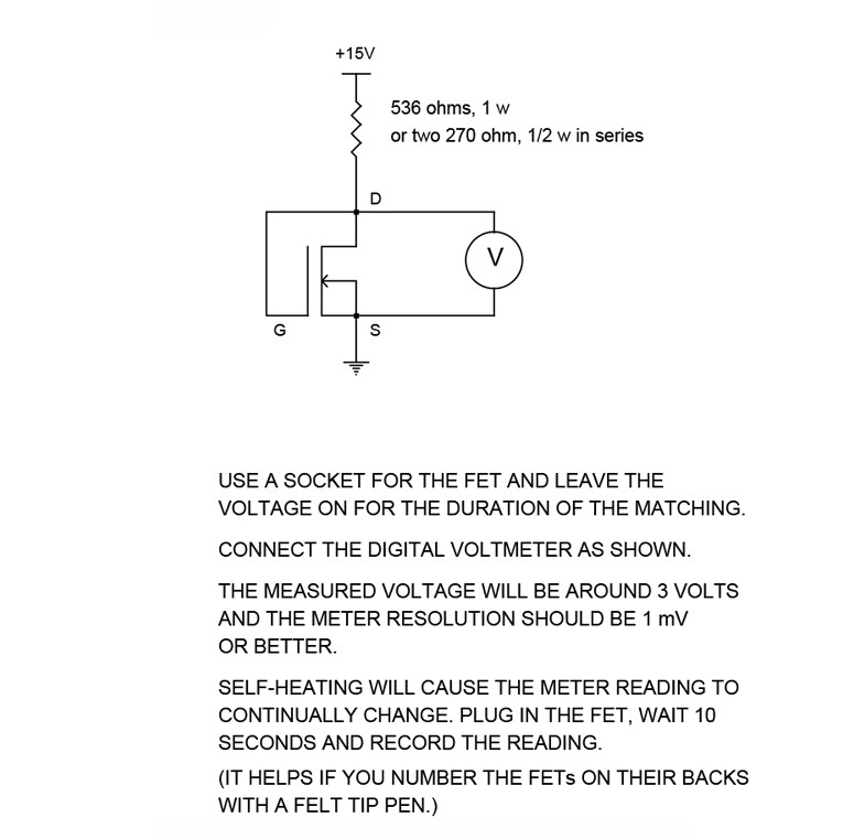
As Mr. Simon mentions, Q1 and Q2 should be matched to minimize the DC offset voltage at the output. A simple way to do this is with the circuit in the Matching sidebar. Buy at least ten and preferably 20 of the IRF510s or IRF610s so you can find some closely matched pairs. (They are rather inexpensive.)
Construction
Parts placement inside the rack mount enclosure is not too critical, and the photos will help, but a few points: position the power transformers as close as possible to the front panel to get them as far as possible from the circuit boards. Also, twist the leads, especially on the primary side.
There are 1/8" diameter mounting holes in all four corners of the circuit board. It’s helpful to attach 1/2" long, 4-40 threaded hex nylon spacers to each corner to make it easier to locate where to drill the mounting holes in the copper heatsink bar. Use a #43 drill with some cutting oil because the copper bar is a bit tough to drill. Then tap both holes 4-40. When doing the final assembly, the two front spacers are not needed. The Q4 and Q5 mounting screws will provide plenty of support, which also avoids stressing the boards as components heat and cool during use.
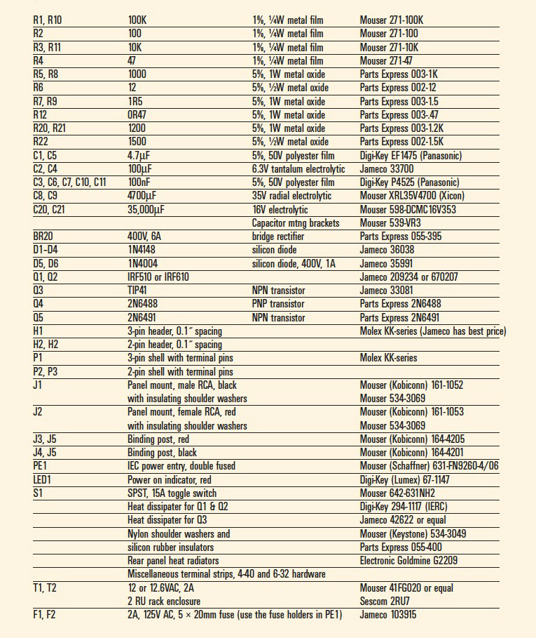
Although most components are the same as in the original article, I’ve included a parts list for completeness and to note the few changes. I used 22 AWG stranded Teflon insulated wire for all the wiring. Number 22 is the largest size that comfortably fits the Molex KK-series connectors.
A Change
Summertime in southern New Mexico is warm so the air conditioning runs most of the time. Not much background noise, but a little. On one cooler and cloudy day recently, the A/C was off and I noticed a slight hum from the main speakers coming from the Simon amp. So I took it out of the rack and measured 120Hz at 40mV p-p on the left channel and about 44mV p-p on the right. Of course, it’s not audible when the music starts, but a purist might object.
I replaced the 2900μF caps I originally used at C20 and C21 with 35,000μF 16V units. The hum went down to 10mV p-p (left) and 15mV p-p (right). I can still hear a bit of hum if I put my ear very close to the right side speaker but it’s now inaudible from the listening position.
These caps are the same diameter (and just a little taller) than the 2900μF units so the replacement went easily. The new caps are in the Cornell Dubilier DCMC-series. Not only do they pack a large capacitance in a small package but they can handle high ripple current too. In this case, up to 6.1A at 105° C.
A fundamental problem with single-ended amps is they have virtually no power supply ripple rejection (PSRR). Balanced amps, because they are balanced, usually have quite a high PSRR so smaller value filter caps work well.
In conclusion, I can say I’m very pleased with this amp and have been listening to it daily for several months. Friends won’t believe me when I tell them it’s only 1W and five transistors per channel. aX
Sources
If you can find the copper rod and bar locally, that’s fine. If not, you can order it from:
Small Parts, Inc.
www.smallpartsinc.com
(No minimum order)
 Electronic Goldmine
www.goldmine-elec.com
Jameco Electronics
www.jameco.com
Mouser Electronics
www.mouser.com
Parts Express
www.parts-express.com
Rack-mount enclosure now available at Wolgram Engineered Plastics,
www.wolgrammfg.com
Side Notes
This project is based on a previous audioXpress article: “A Solid-State Single-Ended Power Amp” by Ed Simon, published in the April 2006 issue.
This article was originally published in the old audioXpress website as a PDF, but was never reposted. We made it available again here with updated references and links.
The supplementary files, are again available with this article (check download attachments below)
Ron Tipton adds: "I'm still using this amp to drive my 10-speaker line arrays."
Contents of the simon-zip file
contents.txt
simonamp.pdf - Notes on the modified amp with parts list and sources
simon1.pdf - Circuit diagram of modified amp
simon2.pdf - Circuit diagram of modified power supply
simon.pcb - Circuit board in Circad format*
simon.pdf - Circuit board parts placement
simon1.jpg - Rack mount amp front panel photo
simon2.jpg - Rack mount amp read panel photo
simon3.jpg - Inside photo
simon4.jpg - Inside photo showing Q4-Q5 heat conduction bar
simon.cir - SPICE model file
matching.pdf - Notes on matching Q1 and Q2
mosfet.lib - SPICE library file
TIP41C.lib - SPICE library file
TIP42C.lib - SPICE library file
2N6488.lib - SPICE library file
2N6491.lib - SPICE library file
diode.lib - SPICE library file
* You can view and print the pcb file with a free version of Circad from www.holophase.com
TDL Technology, Inc
5260 Cochise Trail
Las Cruces, NM 88012 USA
www.tdl-tech.com


