This control unit design features high-perveance tubes in the phono and in the line amplifier. The phono section contains two 6N1Ps and one 6922, 33 mu triodes. The phono amplifier has an output voltage of 0.68 V RMS with an input voltage of 3 mV/1 kHz. The line amplifier uses three 5687s with a mu of 12; the 5687 is equivalent to a paralleled 6SN7. The 5687s are connected in a paralleled SRPP circuit providing a flat frequency response of 20 Hz to 40 kHz.
The 5687 SRPP circuit contains a “bass enhancement control” that uses a frequency limiting capacitor and inverse negative feedback to adjust (decrease) the level of the frequencies from 400 Hz to 20 kHz but has no effect on the frequencies from 10 Hz to 100 Hz.
This control is especially designed for tone control “haters.” The control only enhances bass frequencies a maximum of 6 dB by changing the level of inverse negative feedback. This bass enhancement control is designed to convert tone control “haters into believers,” at least with this circuit.
I never use tone controls, but my son Stephen expressed an interest and need for modifying the sound when playing records. I knew the traditional tone controls were not the way to go, as I tried them all and was very aware of their limitations. I gave this problem quite a lot of thought and arrived at the solution by thinking “outside the box.”
As mentioned, I didn’t enhance the bass frequencies but instead used negative feedback and a frequency selective capacitor to reduce the level of the 400 Hz to 20 kHz frequencies.
The variable feedback control also had the dual purpose of injecting a small amount of negative feedback at the user’s discretion.
This control, with its very subtle means of simultaneously varying frequency and applying negative feedback, gave the result a discriminating audiophile can accept.
The control unit uses a total of six tubes three in the phono section and three in the line amplifier section. A commercial unit using the same number of tubes as the unit described here would typically sell for $3,000, which is a fair price when you consider that constructing this unit requires a minimum 100 man-hours.
This all-tube control unit will be competitive with or outperform some of the most expensive phono/line amplifiers. The three 5687s used in the line amplifier in a paralleled SRPP circuit normally would use four tubes, but I used two tubes (each section connected in parallel) for the active amplifier device and separate sections of a single 5687 as the load and power control. Thus, I eliminated one 5687.
Of interest: The phono amplifier in this article does not use high-mu 12AX7s or 12AT7s, but rather linear, low noise, high-perveance 6N1Ps and a 6922, all with a mu of 33. During the early days of the introduction of magnetic phono cartridges in commercial radios, the 12AX7s were developed to eliminate a medium mu tube and thus save the radio manufacturers money.
The implementation of the 12AX7 was based on cost constraints and not technical excellence. Many manufacturers who employ the 12AX7 for costly hi-fi use do not seem to be aware that they adapted a low-cost concept in their product. To provide technical excellence in phono amplifier design and ensure a superior sound, vacuum tube phono amplifiers should be limited to tubes with a maximum mu of 40.
Features
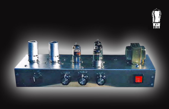
The control unit (see Photo 1) has a remote 12V AC/8A power transformer ($25) and a chassis-mounted transformer ($7.99). The 12 VAC power transformer is located remotely from the control unit chassis to ensure low-noise operation. This 12V AC transformer provides power to operate a 12 VAC (input) to 120 VAC (output) chassis-mounted power transformer and a full-wave, bridge-rectifier to furnish power to the filaments of the control unit.
The 120 VAC output of the chassis mounted transformer “feeds” a fullwave, voltage-doubler, bridge-rectifier and provides 180 VDC output. Because the remote transformer delivers most of the power to operate the control unit, the undesired magnetic noise of this transformer is isolated from the control unit chassis. The chassis-mounted power transformer operates at a low power level and thus generates a low level of magnetic noise.
The control unit (see Photo 2) has a two section, six-position selector switch. Five positions are used for line-level operation, while the sixth position can be used for a phono amplifier. A DPST power switch is used to turn the control unit and remote power amplifier on or off.
The control unit operating in the line level or phono mode with volume control three-fourths on is “dead quiet,” and your ears cannot detect noise inches away from the speakers. The realism of sound reproduction of the control unit with the phono and line-level amplifier operating is excellent. A 100k volume control (P1) with a 40% tap, a 250 kW balance control (P2), and a 500 kW bass enhancement control (P3) are employed as the basic operating controls.
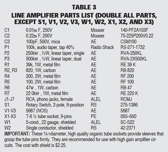
Line Amplifier
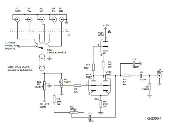
The line amplifier (see Figure 1) uses a 5687 paralleled SRPP circuit with a voltage gain of 10. The paralleled 5687 SRPP circuit provides an output impedance of 2600W and obviates the need for a cathode follower. The distortion at the output of a paralleled 5687 SRPP driving either a 100 kW or a 10 kW load is unchanged at 0.18% at 2.5 V RMS/1 kHz.
The heaters are operated at 12 VDC that is supplied by a filtered, full-wave bridge-rectifier. The plate of the SRPP connected 5687 is operated from a supply voltage of +180V DC.
The circuit of the paralleled 5687 SRPP amplifier is simple and uses only one coupling capacitor in its output.
The 5687 is especially suited for use as a line amplifier with its 3.6 VDC cathode bias and its 0.18% distortion at 2.5 V RMS output. This provides considerable headroom at both the input and the output of the tube and ensures no clipping will occur during reproduction of music peaks.
The noise of the line amplifier is 0.3mV with volume control (R1) full on and the input open, non-shorted. (The noise measurement is made using a DMM, Radio Shack, 22-168A.) All noise and ripple measurements throughout this article use a DMM with shielded test leads.
The distortion from 30Hz to 15kHz of the line-level stage is typically 1.0% at 15 V, 0.64% at 10 V, 0.52% at 7.5 V, 0.32% at 5 V, 0.25% at 3 V, and 0.1% at 1 V RMS output.
Clipping of the paralleled 5687 SRPP circuit occurs at 30 V RMS. The 100 Hz and 1 kHz square waves are reproduced perfectly and the 10kHz square wave shows only a slight amount of “rounding,” as is expected with its high-end frequency range of 100 kHz. The normal operating range of the line amplifier is 0.5 to 3 V RMS. The frequency response of the line amplifier is flat at 5 V RMS from 20 Hz to 40 kHz, tapering to 4.2 V RMS at 100 kHz when feeding a 6' audio cable.
Of interest: A paralleled 5687 has approximately the same characteristics as the 6H30. You could adapt this circuit for line amplifier use only and eliminate the phono section, which would greatly simplify the construction process.

Bass Enhancement Control Circuit
The bass enhancement control circuit (see Figure 1) operates by frequency selective capacitor 0.01 mF (C1) and negative feedback that is applied between the plate and grid of 5687 (V1). The 0.01 mF capacitor blocks all frequencies below 400 Hz from entering the negative feedback loop of the 5687. The 0.01 mF capacitor is fully functional to all frequencies above 400 Hz.
The level of the negative feedback is controlled by 500 kW potentiometer (P3), and control does not start until the potentiometer setting is rotated below 300kW. The maximum amount of feedback that can be applied to the 5687 is controlled by a 39 kW resistor (R1). Resistor R1 is chosen to provide a typical
maximum reduction of the input signal from 1 V to 0.5 V.
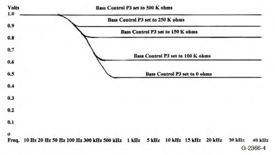
The feedback is applied to the 40% tap of volume control potentiometer (P1) that essentially applies the feedback directly to grid (V2). To observe the feedback effect as feedback control (P3) is set to 250 k, 150 k, 100 k, and 0 W , refer to Figure 4. Keeping the output voltages constant at 20 Hz makes it easier to evaluate the effects of the inverse feedback at the four potentiometer settings. As the volume control is rotated towards the three-quarter fully open position, the feedback is automatically reduced by the action that occurs at the 40% tap of volume control P1. This reduction in the bass enhancement as the volume level is increased is in accord with the Fletcher-Munson response curve. Also of interest, as the feedback control is increased to a maximum setting, you can observe from the bass enhancement chart (see Figure 4) that the slope from 100 Hz to 400 Hz is greatly increased.
The advantages of this control over the traditional tone controls:
1. Does not require a dedicated tube; uses existing tube. Feedback is employed between grid and plate.
2. Feedback is limited to a typical 6dB; therefore, bass enhancement is 6 dB maximum, not 12 to 18 dB as in conventional circuits.
3. Bass enhancement is limited to 10 to 100 Hz, slope from 200 to 400 Hz, and feedback attenuated frequencies are flat from 400 Hz to 40 kHz. When traditional circuits are used, the frequency alteration extends beyond 2 kHz.
4. The application of inverse feedback with this circuit reduces the distortion for all frequencies from 400 Hz to 40 kHz. In traditional circuits, the distortion is increased.
5. No phase anomalies as in traditional circuits.
The only negative is that operating this circuit requires the use of negative feedback, but these effects are only noticeable as the feedback control is rotated beyond the three-quarter way mark.
The feedback control (P3) is inoperative when set above 350kW or fully open position and thus has no effect on the frequency of the line amplifier. This method is simpler and less expensive than installing a switch to disable the feedback function.
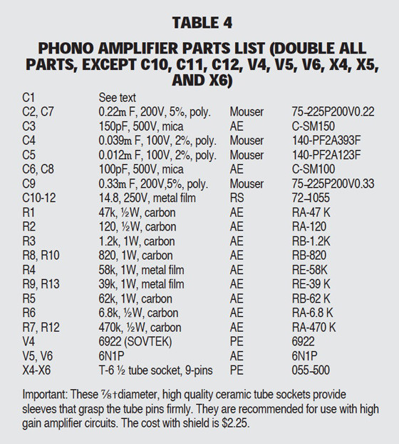
All-Vacuum-Tube Phono Amplifier
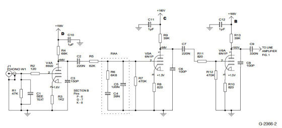
The phono amplifier (see Figure 2) uses two 6N1Ps and one 6922. It features a non-feedback design with a passive RIAA network. The noise is less than 2.4 mV at the output and sensitivity is 3 mV for 0.68 V RMS output at 1 kHz. The distortion of the first, second, and third stages is less than 0.15% from 20 Hz to 20 kHz
with a 0.4 V RMS output in each of these stages. The distortion measurements are made bypassing the RIAA circuit.
The frequency response of V4, V5, and V6 with Inverse RIAA Network connected to the input of V4 is shown from 20 Hz to 20 kHz (see Figure 5). I used an Inverse RIAA Network (Norman L. Koren, 2/97 GA) to ensure that the circuit components chosen for the RIAA network provided a flat frequency response. If an inverse RIAA network is not available, the information provided in Table 2 may be used to determine the accuracy of the phono amplifier RIAA network.
With 3mV, 1kHz fed to the input of V4, the output at V4 should indicate 42mV. The loss through the RIAA network drops the 42mV to 3.6mV at the input of V5. The voltage at the output of V5 is 58mV RMS.
The 58mV output of V5 feeds the third stage V6 and the output of V6 is 0.68V. The output of the third stage V6 feeds the line amplifier (5687). The output of the paralleled 5687 line amplifier is 6 V RMS (5687) with 3 mV, 1 kHz at the input of the phono amplifier. With a record playing, the output of the line amplifier typically swings from 1 to 9 VAC.
The noise at the output of the line amplifier with a six position, rotary switch set to the phono position is typically 5mV (with the 600W load of the audio oscillator across the phono input and the audio oscillator turned off, simulating the phono cartridge load). Capacitor C1 tailors the high-frequency output of the magnetic pickup, and R1 provides the proper load to the cartridge.
The value of capacitor C1 is determined from the cartridge-recommended capacitance value. It is obtained by subtracting the cable capacitance, the input circuitry, and amplifying device capacitance from the cartridge-recommended capacitance value. When a range is given for the cartridge-recommended capacitance value, it is suggested the lowest figure be used for the calculation. A further refinement of the selection of the phono cartridge capacitance is presented in Raymond A. Futrell’s article, “LP Terminator” (audioXpress, January 2003).
Futrell’s “simplified” formula, which assumes the loading resistor is 47 kW , Q, 0.707, and the mH value is above 100 (moving magnet (MM) cartridge) is:
C (in pF) = L (mH) times 0.225.
This simplified formula only applies to MM phono cartridges.
C = total value of shunting capacitance paralleling the coil of your cartridge.
Remember, the typical shielded phono cable has a capacity of 25 to 37 pF per foot (confirmation requires measurement because some cables have much higher capacity/per ft. values and would be unusable). Also, a 6922 has a typical 30 pF of capacitance and a high mu vacuum tube input circuit about 50 pF of capacitance. This phono amplifier is designed for MM cartridges having outputs of 3 to 8 mV.

Cartridge Capacitance Calculation
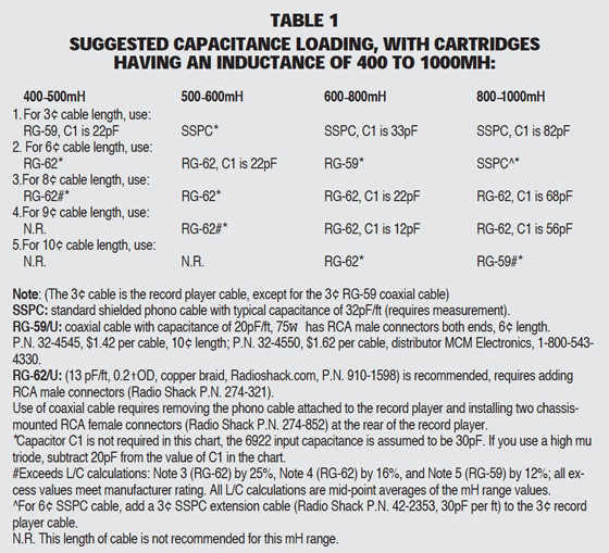
A simplified method of tailoring the cartridge for the proper loading capacitance is to use the chart on Table 1, which is derived from Futrell’s calculations.
When the manufacturers of phono cartridges state the value of the recommended loading capacitance, they are including the capacitance of all the input circuitry from the phono cartridge to the input of the 6922 vacuum tube (including the capacitance of the 6922, about 30 pF). Also included is the capacitor at the input of the phono amplifier and the capacitance of the phono cable. When this concept is accepted, the manufacturers’ recommended value of the loading capacitance becomes acceptable
criteria for understanding the capacitance rating system.
Most manufacturer capacitance rating systems appear to be valid or a reasonable compromise when this additional insight into capacitance loading is understood. You must review your system to ensure the total capacitance conforms to the cartridge manufacturer’s recommended total loading capacitance value. If your total phono system capacitance matches or is less than the cartridge manufacturer’s recommended loading capacitance value (but not less than the value determined from Futrell’s L/C formula), you’ll obtain good wide frequency sound from your phono cartridge.
A review of the phono amplifier, phono cable, and input circuitry capacitance will in most cases reveal that your system is responsible for the major capacitance imbalance of the phono cartridge capacitance loading.
After you have confirmed your system meets the recommended loading capacitance of the manufacturer, but you still desire to improve your system, then proceed to Futrell’s (L/C resonance) mathematical formula for further refinement of the cartridge capacitance loading process.
Important: If you use the chart on Table 1 to match your phono cartridge to your existing phono system, the input loading capacitor of the phono amplifier (if there is one) must be disconnected. This phono amplifier did not experience RF interference using 3 to 10’ lengths of SSPC or coaxial cable.
If you have costly video or audio cables with low capacity values compatible with RG-59, you can use them in this application. The capacity of these costly cables must be measured, as they do not offer capacity values. All audio cable and many phono cartridge manufacturers prefer to withhold detailed specification information.
Important: The five steps illustrated in Table 1, the manufacturer’s recommended load capacitance, or Mr. Futrell’s mathematical concept may be used in selecting loading capacitance values.
Note: In the pamphlet supplied with the cartridge, the manufacturer does not specify that a given capacitance be added to the cartridge circuit, only that a total recommended amount of capacitance is present.
The cartridge specifications are required for proper integration and mating to the phono amplifier. It is important to know the standard shielded phono cable (SSPC) used in your system is 25 to 35 pF per foot. Do not assume it has standard capacity values, it could have very high capacity values. If the phono cable in use is attached to a record player and is 3’ in length, it probably has standard capacity values.
If, however, your system requires a 6-10’ cable, make certain that it is a low capacity cable. A high capacity cable could make matching your cartridge with the correct loading capacitance impossible. My chart simplifies the cable selection process.
My phono system uses a 10’ RG-59U cable connected to a Stanton 680HP phono cartridge (930mH) and is compatible with Futrell’s L/C concept and my chart. After making this modification, I noticed a definite improvement in the sound of my audio system, particularly the high frequencies. Also, the 10’ coaxial cable is free of hum/noise and RF interference.
This phono amplifier has an output of 0.68 V RMS at 1 kHz with a 3 mV input signal, loaded by a 100 kW volume control and 250 kW balance control. The signal is higher than that of a Sony CA9ES CD player. The volume control is set at the one-quarter to one-third position for living room “listening” levels when in the phono mode. This confirms the high output design of this all-vacuum tube unit.
The description and function of the individual circuit components of the phono amplifier (see Figure 3) follows:
• Capacitor C1 (Table 1) tailors the high-frequency output of the magnetic pickup, and R1 provides the proper load to the cartridge.
• Resistors R2 and R5 provide resistance de-coupling.
• Capacitors C4, C5 and resistors R5, R6 form the RIAA network.
• Capacitors C2, C7, and C9 are coupling capacitors.
• Capacitor C3 suppresses RF pickup, capacitors C6, C8, C10, C11, and C12 are required to stop unwanted high frequency oscillation.
• Resistors R4, R9, and R13 are plate load resistors, and R3, R8, and R10 are cathode bias resistors, which were chosen to provide low distortion operation for V4, V5, and V6.
Note: You can add a 1000 mH, 14W, RF choke (Mouser P.N. 542-77F102) to the input of the phono amplifier, if needed, for RF suppression. Place the choke between the phono jack and 120 W resistor.
Important: I recommend that you have an audio oscillator (optional) and vacuum tube voltmeter or digital multimeter (DMM). This equipment is essential to ensure proper balance and that gain is obtained throughout the phono amplifier circuit. The 6N1Ps and 6922 provide a very broad frequency response with a detailed and clean output.
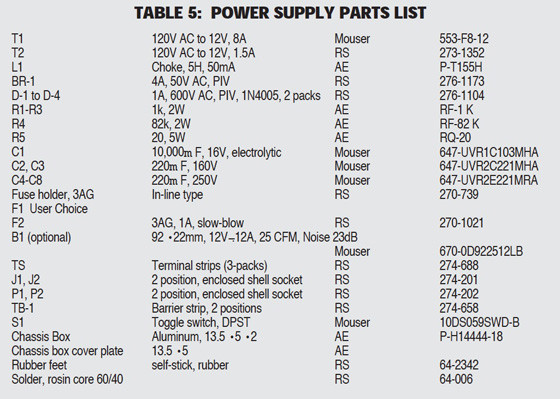
Power Supply
The power supply (see Figure 3) consists of a remote 120 VAC to 12 VAC transformer T1. The transformer secondary is rated at 8 A at 12 VAC, which is conservatively rated to furnish the 3.3 A required to operate the 6N1Ps, 6922, and 5687s. The remote transformer 12V AC output voltage feeds a full-wave, bridge-rectifier that is filtered by capacitor C1. The output of the heater supply provides 12V DC to the heaters with a ripple of 0.32V RMS. The 6922 heater requires voltage-dropping resistor R5 to obtain 6 VDC. The 12 VAC output of the remote transformer also feeds the 12V AC winding of chassis mounted transformer T2.
The 120 VAC output of transformer T2 rated at 1.5A feeds the full-wave bridge (D1 through D4), voltage-doubler rectifier. Voltage doubling is accomplished by capacitors C2 and C3. The choke L1 diminishes the switching transients that occur during the rectification process. Capacitors C4 through C8 are additional filtering devices and provide a low-noise ripple of 0.6V RMS at the +180V DC output. (The noise measurement was made with a DMM using shielded test leads.) Resistors R1 through R3 provide de-coupling. The resistor R4 is the bleeder for the 180V DC output. Transformer T2 is only slightly warm after hours of operating time.
Note: I originally used a 5A rated transformer for T1 but this transformer became quite hot, so I recommend you use 8A transformer (553-F8-12 at $25) from Mouser Electronics. Safety shielding is required for AC line terminals.
Forced air-cooling: Blower fan B1 is optional; if used, locate it at the end of the chassis facing the transformer.
Construction
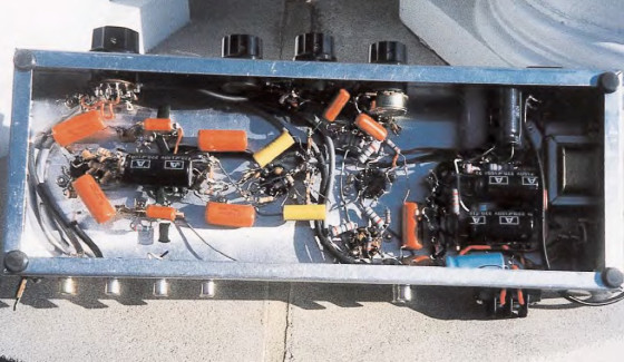
Important: It is imperative that the control unit (see Photo 2) is an unpainted aluminum chassis to ensure that all components are properly grounded. Do not use a painted steel chassis!
All the electrolytic capacitors are grounded at the negative band, except those connected in series. All other components are connected to tube sockets.
In the phono am amplifier section, seven 5-pin terminal strips are required. It is very important that the assembly be tailored around the implementation of the seven 5-pin and three 2-pin terminal strips. Also required are eight spade lugs. Using the terminal strips provides a very simple step-by-step construction
process. It also permits easy changeability of parts. Building the control unit is a fun, easy project using the 5-pin terminal strips, but a “nightmare” using a PC board. The RIAA network components are mounted on a single 5-pin terminal strip.
It is important that all audio runs approximately 3† or more use shielded cable (especially at the input of the phono amplifier) and that the shield is grounded at the input end. It will only be necessary to ground the shielded leads of the phono amplifier at the end nearest the input of the amplifier. The five-conductor shielded cable that connects to the 6-position rotary switch must be grounded at the input end.
Most grounds are made to the center post, 5-pin terminal strip. The use of chassis-mounted solder ground lugs for the cathode and grid resistors and heater grounds are also recommended. The minimum test equipment required for building the phono amplifier and the control unit is a vacuum tube voltmeter or DMM (an audio signal generator is optional).
USEFUL HINTS
1. Tubes V4 and V5 use 2-pin terminal strips for ground and B+ connections. Capacitor C8 of the power supply is located at V4, 2-pin terminal strip.
2. The B+ and B-of BR-1 (power supply) is connected to a 2-pin terminal strip. The 12V AC leads are soldered directly to the BR-I diode AC leads.
3. Capacitors C4 through C7 and R1 through R3 are secured to a 5-pin terminal strip. Capacitors C10, C11, and C12 are connected to the junction of 6922 and 6N1P plate resistors and ground.
4. Diodes D1 through D4 and capacitors C2 and C3 are secured to “back-to-back” mounted 5-pin terminal strips.
5. The 12V AC input power, 12V DC tube heaters wires, and capacitor C1 are connected to a 5-pin terminal strip.
6. A 5-pin terminal strip is used at the output of V6 to secure capacitor C9, B+, and plate resistor R13, grounds of shielded cable.
Warning: Dangerous voltages are present, exercise extreme caution when working on the control unit and never leave the control unit upside down when children are present.