Similarities and Differences
First, let us look at the similarities in testing loudspeakers and headphones. The set-up essentially consists of an electroacoustic measurement system, some kind of ear simulator containing a reference microphone, and the device under test. A test signal is sent to the transducer (headphone), which in turn is measured by a reference microphone in a coupler.
The basic measurements made on headphones are very similar to those made on loudspeakers. These include frequency response, phase (polarity), distortion (THD and Rub & Buzz), and impedance.
In both cases, the test signal is usually a swept sine wave, and the level can vary. Some set the drive level to achieve a certain sound pressure level at a given frequency; others choose the level that equates to 1 mW of power. Certain products may necessitate testing the frequency response at one level and performing a second, higher level test for distortion.
Now, let us look at the differences. The primary difference in the test set up between a loudspeaker and a headphone measurement is in the way in which the transducer interacts with the microphone. Whereas loudspeakers are tested in open air, a headphone or earphone must be presented with an acoustic load that simulates the human ear. It is common to compare the left and right-channel frequency response. Large differences at certain frequencies can be very audible in a stereo device, even though the individual responses may be within specification. Sometimes, electrical characteristics such as crosstalk may also be measured.

Considerations
Before beginning to test headphones, there are two major considerations that need to be taken into account— correction curves, and the acoustic seal. These both have an effect of the frequency response. The latter also affects the repeatability of measurements.
Coupler Correction Curves
Loudspeaker engineers are familiar with the ideal frequency response for a loudspeaker measured in the free field being a flat line (see Figure 1a). For headphones, however, this is not the case. Headphone measurements are taken at what is known as the Drum Reference Point (DRP) — a point representing the human eardrum. Figure 2 shows where this is on a Head & Torso Simulator (HATS). If you were to measure the same loudspeaker that produced the flat free-field response curve in Figure 1a at the Drum Reference Point, the frequency response would look like Figure 1b. In other words, for a headphone to sound like a loudspeaker with a flat frequency response, it must produce a frequency response curve like Figure 1b.
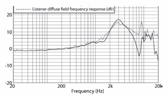
This frequency response curve is a correction curve, or transfer function that represents the effects of the head, torso, pinna, ear canal and ear simulator. To further complicate matters, different correction curves are applied according to whether your measurements are made in the free field (anechoic room) or diffuse field (reverberation room) (see Figure 3). For the most part, like loudspeaker measurements, the free field is used. Typically, when making measurements, the subtraction of the correction curve from the actual measurement can be carried out in your test software, so that your output frequency response is shown as the familiar straight line.

Headphone/Ear Seal
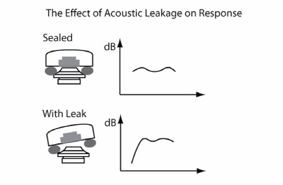
Another issue that needs to be addressed when testing headphone is the acoustic seal, or leakage. Realistic headphone measurements (using a HATS or similar) have a certain degree of leakage as the headphone does not fit tightly to the pinna. This has an effect on the frequency response, with a demonstrable loss at low frequencies (see Figure 4). Although realistic, it affects the repeatability of measurement. In the R&D lab, this is compensated by repeating the measurement multiple times, removing and repositioning the headphone between each measurement and averaging; on the production line different couplers and fixtures are used to offer a more repeatable seal—these are discussed in more detail below.
Different Types of Headphones
First, before we look at test configurations for headphone testing.
Let us look at exactly what we are measuring. Headphone is a broad term, which covers several different designs of product, each with their unique testing challenges. Headphones fall broadly into four categories (see Figure 5): Circumaural (a large cup that completely surrounds the ear and pinna), Supra-aural (an earpad that sits on the pinna), Earbuds (also known as Supra-Concha), where the transducer rests at the entrance to the ear canal, and In-ear where the sound port sits inside the ear canal.
Although the measurements that need to be made are the same for each of these, the fixturing — a critical part of the test set-up — is different for each type.

A Basic Headphone Test Setup
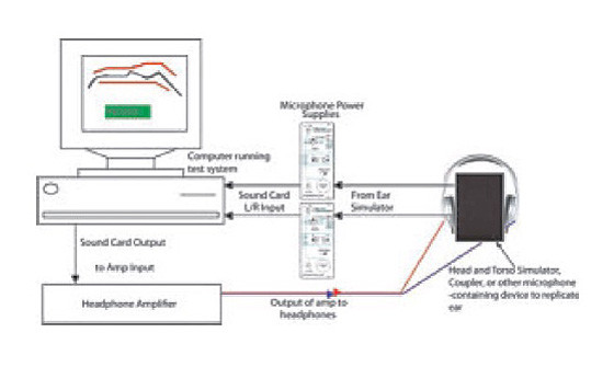
Figure 6 shows a headphone test set-up (suitable for all types of headphones) using a PC and soundcard-based measurement system. Although hardware-based systems may, of course, also be used, a soundcard offers more than sufficient accuracy for testing headphones, and such a system is usually less expensive.
As you can see, the only part of this setup that will be unfamiliar to those accustomed to loudspeaker measurements is the “black box” that represents a device that simulates the ear (and replaces the microphone in a loudspeaker setup).
What’s in the Black Box?
The equipment in the black box can be a multitude of things, depending on whether you are testing in the R&D lab or on the production line, your budget, and the type of headphone you are testing. Essentially it will be the microphone-containing device you have selected which simulates the human ear with some degree of accuracy, and appropriate fixturing to ensure repeatable results with the particular headphones you are testing. This is perhaps the most complex part of this setup, and the one which poses the most challenges to engineers.
In order to select the most appropriate ear simulation device, the first question that must be asked is whether the test should be a realistic simulation of actual use (commonly performed in development) or a highly repeatable test capable of differentiating defective units from good ones (production). When developing a product, it is desirable to have a means of measuring under conditions that the end user will experience.
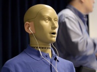
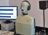
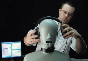
A head-and-torso simulator provides this level of simulation, as it is equipped with artificial ears, which mimic the acoustic characteristics of the human ear, as well as artificial pinnae, which mimic the way a headphone would fit on a real person. The fit of headphones and earphones can vary from person to person and even from one use to another, and can drastically change the user’s listening experience. Testing on a head-and-torso simulator (see Photo 1) can reveal this variability between fit and acoustic performance. This lack of repeatability is realistic and useful to understand how fit impacts the sound quality. Engineers will commonly take several measurements and average them to account for it. Head-and-torso simulators are expensive (upwards of $20,000), so some R&D laboratories use less expensive (but with the expected performance trade-offs) alternatives such as cheek and ear simulators, couplers, simplified pinnae, etc.
Head-and-torso simulators are not suitable for production line use for two reasons. As discussed, the fit may be slightly different each time, which makes it very difficult to get repeatable results on the production line, and also the cost is prohibitive. This is overcome by designing a product with a known response using simulators (such as the Head & Torso) that accurately replicate a human, and then basing production line testing around ensuring that all products coming off the production line match that ideal product. This means that different test methods can be used.
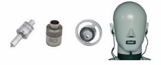
In production and QA it is important to use a fixture that is highly repeatable and can produce consistent results. An acoustic coupler, which is essentially a metal chamber that replicates the ear canal, is most commonly used. Couplers vary significantly in their complexity and cost. The most commonly used production coupler is a 2 cc coupler, which is simply a 2 cubic centimeter cylindrical chamber which is an approximation of the ear canal impedance. More complex (and therefore more expensive) is an IEC 711 coupler which has a multiple internal chambers that more accurately replicate the acoustic impedance of a human ear.
Although the characteristics of this coupler are close to the human ear in the lower frequency ranges, above 8 kHz it is not well defined. No manufacturer has created a coupler that offers a truly accurate representation of human hearing above 8 kHz because human ears vary more at high frequencies. For manufacturers who want to go one step further than a coupler, a pinna with simplified geometry is available. Although not shaped like an ear, it is built to allow some degree of replication of the acoustic leakage that would occur with a real ear. Photo 2 illustrates these devices.
Even with the simpler geometry of a coupler, it is still hard to get repeatable results, and most production line applications rely on custom fixturing to offer greater repeatability of mounting for a controlled seal. Usually a fixture is custom built for a specific product to ensure repeatable attachment to the coupler.
For circum-aural and supra-aural headphones some sort of clamp is used to apply a consistent pressure, which aids repeatability.
Earbuds and in-ear earphones typically use a gasket of some sort to create a seal. This seal produces more accurate low-frequency response and has the added benefit of reducing the influence of ambient noise on the test.
Headphone Tests
Now that we understand the test set-up, lets talk about what we typically measure with a headphone. If you are buying a new test system for testing headphones, you should consider what and how you want to test before purchasing, as it has a bearing on the number of inputs and outputs you will need on your soundcard or test system. If you are testing a stereo pair simultaneously, you will need a two-channel soundcard just for the acoustic tests. If you want to also simultaneously measure electrical characteristics such as impedance, you will need four channels. If you already have a two-channel system, you can measure impedance sequentially rather than simultaneously, although it will be a little slower.
A typical basic R&D test using a head and torso simulator for a stereo headphone pair would consist of playing a 1/12 octave stepped sine sweep from 20 to 20 kHz and measuring the harmonic distortion and fundamental frequency response.
Correction curves would compensate for the free-field response from 0° incidence to the nose to the eardrum. Post-processing can then be used to compare the left and right earphone responses and show the difference curve, both for magnitude and phase.
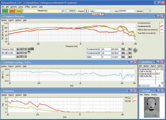
With a four-channel analyzer, this test may be expanded with the addition of a couple of reference resistors to measure impedance of the headphones at the same time. Other options for more detailed testing would include measuring intermodulation and difference frequency distortion, or measuring maximum SPL using the distortion level to set the upper limit. Naturally, each company wants to test their products slightly differently, and most test and measurement systems offer the ability to customize tests. A typical production line test would be similar, but a custom compensation curve, based on the coupler and fixturing would need to be applied. On the line, impedance, if measured, would be done simultaneously for speed reasons. Figure 7 shows an example test report for a R&D headphone test carried out in SoundCheck, a soundcard based test system that is used in the R&D lab and on the production line for measuring headphones.
Standards
IEC 60268-7: Sound System Equipment — Part 7: Headphones and Earphones is probably the most comprehensive standard on headphone testing. It talks about how to classify earphone types (e.g., supra-aural versus supra-concha) describes various couplers and acoustic ear simulators, defines free-field versus diffuse field conditions, and describes how to test headphones. It specifies the standard test level to be 94 dBSPL at 500 Hz or 1 mW at the earphone’s rated impedance and defines how to measure the rated impedance. A copy of this standard costs approximately $200, and may be purchased from the IEC website.
Conclusion
This article covered the basics of headphone testing, focusing on those issues applicable to all types of headphones. In Part 2, a follow-up to this feature, we will discuss special cases of headphone testing, specifically Bluetooth and USB headphone testing, noise-cancelling headphones, and Max SPL measurements.
These are complex subjects requiring the use of different test signals and compensation for time delays, dropouts, and other characteristics inherent to these special types of headphone.
Article originally published in Voice Coil, December 2011.