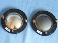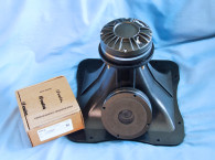
The aluminum alloy 475PB appeared in Test Bench in the January 2019 issue. For this review, I happened to have both versions of this ferrite magnet compression driver, the aluminum diaphragm 475PB and the beryllium diaphragm 475BEPB, so in this explication I will give you a partial comparative analysis of the two different diaphragms.
As you might expect, the 475BEPB has a similar set of features as the 475PB. This includes a 1” throat diameter, a 134mm × 19mm ferrite magnet motor, high temperature 44.5mm (1.7”) diameter high temp polyimide voice coil former wound with copper-clad aluminum edge-wound ribbon wire voice coil, 50W AES power handing above 800Hz (100W program power handing), a self-aligning field replaceable diaphragm assembly, copper shorting ring located in the gap area, and the most important feature—a Materion beryllium diaphragm over a three-slit phase plug. Other features include a minimum recommended crossover frequency of 1.2kHz, milled and polished steel front and back plates, plus gold-plated color-coded push terminals.
Radian does not produce horns for its compression drivers, so for this body of testing I employed a Faital Pro LTH102 60°H x 50°V hybrid tractrix elliptical flare horn. This horn has been previously used to review compression drivers in Test Bench (see Voice Coil April 2015), so I will not perform the vertical SPL plots or the horizontal and vertical polar plots. However, Figure 1 and Figure 2 display the horizontal and vertical LTH102 horn polar plots and Figure 3 shows the directivity diagrams.


I begain testing the Radian 475BEPB-8/LTH102 combination using the LinearX LMS analyzer to produce the 300-point stepped sine wave impedance plot shown in Figure 4, with the solid black curve the ferrite motor Radian 475BEPB mounted on the Faital Pro LTH102 horn and the dashed blue curve represents the compression driver without the horn.

With a 6.05Ω DCR (Re), the minimum impedance of the 475BEPB/LTH102 was 6.58Ω at 3.9kHz. Results for the 475PB impedance, depicted in Figure 5, were similar with a 6.3Ω DCR with the minimum impedance of the 475PB/LTH102 combination of 6.23Ω 3.5kHz.

For the first set of SPL measurements, I sequentially free-air mounted the Radian 475BEPB/LTH102 combination and the Radian 475PB/LTH102 combination without an enclosure and measured the horizontal on- and off-axis 0° to 60°, in 15° increments frequency response at 2.0V/0.5m normalized to 2.83V/1m, using the Loudsoft FINE R+D FFT analyzer and the GRAS 46BE ¼” microphone (courtesy of Loudsoft and GRAS Sound & Vibration).
Figure 6 illustrates the on-axis frequency response of both the compression driver/horn combinations, which as can be seen, are rather similar. Both response curves, aluminum and beryllium have a smooth ±2dB from 2kHz to 20kHz (along the sloping elliptical horn response) with no major anomalies extending to 30kHz.

Figure 7 depicts the 475BEPB on- and off-axis (0° to 60°) responses in the horizontal plane. Figure 8 displays the normalized horizontal plane response. Figure 9 shows the on- and off-axis (0° to 60°) response in the horizontal plane for the 475PB aluminum diaphragm driver, and the normalized version is shown in Figure 10.


Figure 11 illustrates the two-sample SPL comparison showing the two Radian 475BEPB compression drivers less than 1dB differential throughout the operating range of the transducers to 20kHz (the 475PB samples were as closely matched).

For the remaining series of tests, I initialized the Listen AudioConnect analyzer, with SoundCheck 20 software, and the Listen ¼” SCM microphone to measure distortion and generate time-frequency plots (courtesy of Listen, Inc.). For the distortion measurement, the 475BEPB/LTH102 and 475PB/LTH102 combinations were again mounted in free-air in the same manner as was used for the frequency response measurements, and the SPL set to 104dB at 1m (2.13V for the 475PB and 1.92V for the 475BEPB determined by using a pink noise stimulus generator and the internal SLM in the SoundCheck 20 software).
I then measured the distortion with the Listen ¼” measurement microphone located 10cm from the mouth of the horn. This produced the distortion curves for the 475BEPB shown in Figure 12 and the disortion curves for the 475PB shown in Figure 13 (red curve=second harmonic, blue curve= third harmonic).


Following this test sequence, I set up SoundCheck 20 to generate a 2.83V/1m impulse response for the two driver/horn combinations and imported the data into Listen’s SoundMap Time/Frequency software. Figure 14 and Figure 15 show the resulting cumulative spectral decay (CSD) waterfall plots for the 475BEPB and the 475PB, respectively. Figure 16 and Figure 17 show the Short Time Fourier Transform (STFT) plots for the 475BEPB and the 475PB, respectively.


After reviewing the results, the objective measurements for both the 475BEPB-8 beryllium diaphragm version and the 475PB aluminum alloy version are fairly similar. Obviously, the subjective timbre and detail of these two transducers are definitely different. However, from my own extensive design experience, when it comes to high-frequency drivers, beryllium is certainly a strong favorite of mine because of its musical neutrality and detail. That said, a few years ago I designed and built a farfield monitor for my home recording studio that used a Radian 2” exit 950NeoPB aluminum diaphragm compression driver with an Eighteen Sound horn for the high-frequency section and a 15” B&C Speakers 15BG100 low-frequency driver, and its performance, definition, and detail are absolutely outstanding. For more information, visit the Radian Audio Engineering website at www.radianaudio.com. VC
This article was originally published in Voice Coil, February 2023.


