
Today, most speaker engineers do not take a deep dive into the lead-out wire rabbit hole until they are faced with product field failures. To start at the beginning (or more accurately the leading and trailing ends of the voice coil winding), we need to connect to the terminals mounted to the speaker frame. Since the voice coil will be moving and the terminals are on a stationary frame, a flexible wire is needed.
If the magnet wire ends were brought out directly to the tabs, the flexing during operation could eventually result in conductor fatigue and fracture. Keep in mind, this is for woofers, midranges, and full-range drivers, we will get to tweeters further in our tale.
The voice coil conductor (magnet wire) extends out from the voice coil assembly and are sometimes run from where the bobbin is attached to the cone’s inner diameter (ID), and/or anchored to the eyelets in the cone where they are then spiced to a flex wire, which continues to the terminals.
Flex wire whipping, fracturing of lead-out conductors, thermal issues, and corrosion of the solder joints are just some of the failure modes that afflict less than adequate voice coil to terminal implementations. Perhaps a discussion of preventive measures might come in handy. And the lead-out wire construction and “dress” (how the path is shaped between the voice coil leads to the terminals) can just as easily impact performance or even result in failure modes. Let’s look at a couple of examples where speakers came back to meet their maker!
Potential Problems
For tweeters and headphone drivers, the lead wire could unwind a bit from the coil winding on the bobbin and brought out to the terminals. If the wire has a bit too much length, it might whip around and eventually break — but if there is not enough “play,” it can torque and cause rocking. Count on this being more critical and failures hitting sooner if you are using aluminum or copper-clad aluminum (CCAW) magnet wire rather than good old clunky copper. A thin optimum coating of wax silicon or silicon grease on the unsupported voice coil wire helps avoid oxidation, locks-in the lead dress, and damps whipping. However, excessive goo adds mass and could create even more of the problems you are trying to solve.
For woofers and other high excursion applications, tinsel and Litz flex wires are required. Aside from using flex wire, the dress is critical. Whipping can be a problem with high excursion speakers as they require flex leads with large play. But if the flex wires are too long, they can short out, whip, and resonate, resulting in joint fractures and collisions with the cone or spider.
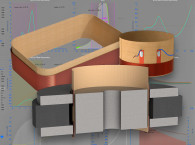
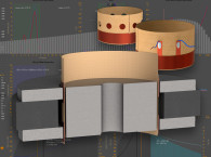
The coil leads usually terminate at a pair of eyelets part way up the cone. This is where the coil lead-outs are joined to the flex wire on the way to the terminals of the speaker frame. As mentioned, to reduce whipping, the length of the flex wire can be reduced by the coil winding lead-out’s exit up the bobbin, captured under the collar and bonded to the cone where part way they are threaded to eyelets in the cone. A bead of glue holds this wire in place, and the flex wire is soldered to the coil lead-out at the eyelet.
Aside from adequate stiffness and damping the flex leads, proper lead wire dress is a must. Usually a pencil (or chop stick) is placed underneath the speaker terminals to form the flex lead radius just before its termination. At various times, the flex wire was located between the spiders on dual spider designs (anyone remember the Gauss pro-sound speakers?).
Typically, the lead-outs are run parallel but best practice is for the wires to be at 180 degrees in opposite directions and the frame terminals to be separate, which minimizes rocking. If the cone/coil is unbalanced due to the torquing from the flex wire, coil buzz and rubs can result. It is recommended only when low moving mass components are used. Production people will say mean things about you after you suggest this approach.
Mogami, Hakken, and others pioneered weaving the flex wire into the spider itself, which can keep you out of trouble, but with an increased BOM cost.

Types of Flex Wire
Flex wire can be characterized by the number of strands and woven constructions. Tinsel wire is produced by wrapping several strands of thin metal foil around a flexible textile core. Because the foil is very thin, the bend radius imposed on the foil is much greater than the thickness of the foil, leading to a low probability of metal fatigue. Meanwhile, the core provides high tensile strength without impairing flexibility.
Typically, multiple tinsel wires are jacketed with an insulating layer to form one conductor. A cord is formed from several conductors in either a round profile or a flat cable. In general, tinsel copper wire may be alloys of electrolyte copper, cadmium copper, or silver-plated copper. Depending on the application, the copper wire may have been flattened and covered using cotton thread, nylon thread, silver thread, Nomex thread, Kevlar thread, or something similar per the requirement — which is at very high flexibility. Then, braiding, twisting, and stranding is done to get final tinsel wire, which is mainly used in speakers, loudspeakers, tweeters, and in earphone cables.
As to the conductor, you should check if the flex wires are ROHS compliant. Cadmium copper is regulated under RoHS and must make up less than 100ppm of a finished alloy (100ppm for cadmium) to be considered compliant. Tensil silver plating on the conductors is preferred if you have the budget.
Litz tinsel wire usually consist of thin and narrow flat strands of varnish-insulated copper wrapped around a cloth core that provides mechanical support and lends flexibility to the cord with individually insulated conductors (forming a bundle). Each thin conductor is less than skin-depth, so an individual strand does not suffer an appreciable skin-effect loss.
Litz wire can be conventionally soldered if the insulation from individual strands is removed, typically with a chemical solvent. Stranded wire with uninsulated strands is a lower-cost alternative to litz wire. The speaker go-to vendor for the full gamut of speaker flex wire is Maeden Innovation.
Let’s look at Estron’s SF2 Litz wire optimized for tweeters, and small full- and mid-range drivers. The SF2 Litz construction combines flexible lead wire with high mechanical damping. Rubbing and resonances are minimized in the interface between the voice coil/cone and the terminal of the speaker driver, which increase temperature stability.
No textile fibers are added in the process for flexibility and to avoid the tendency to contaminate the solder joint. As the lead wire is manufactured from high-purity copper there are no non-conductive materials present to increase the weight of the lead wire. To give flexible characteristics, each individual strand is enameled with a fine layer of polyurethane. The polyurethane enamel not only prevents oxidation but also “tin back-flow” in the soldering process.
Tinsel lead copper wire is created by mixing various metals and alloys and then amalgamating them to produce the most efficient and reliable wires. Electrolyte copper, cadmium copper, silver-plated copper, and others are mixed up with the existing metals to produce tinsel copper wire.

Flex Wire Gauge
For high power woofers, relatively large wire gauges (cross-section mils area) are typical due to the lower electrical conductivity of the alloys used. Pure copper has 97% conductivity, but its flex life is short. Cadmium copper (CDA162) has a conductivity of 95% with good flex life. Tinned copper (Tinsel) is, depending on the vendor’s alloys, around 60% but much better flex life. Cadmium-free copper alloy conductivity is 78% with flex life comparable to tinned copper — but still inferior to cadmium copper. Silver plating is the best practice for any of these constructions.
Textile Fibers
With lead wire, the flex life is the most important issue, with high temperature tolerance as a secondary parameter. Damping fibers reduce whipping (and in headphones and earphones reduce microphonic body noise from getting into the listener’s ears).
Cotton is a short textile fiber, but the flex life/break strength is poor. Polynosic is a modified rayon fiber, often blended with other fibers. It is more stable than a standard rayon meaning it resists shrinking and distortion when wet and is more resistant to wear so it maintains its silky texture longer. Temperature tolerance is 80°C (so high power is out, and even soldering is an issue). Autosplice mechanical attachment is an option—but this short fiber’s break strength is poor.
Dupont Nomex (meta-aramid) fiber offers high temperature tolerance (to 180°C) and is a long fiber with high break load. Teijin-Conex meta-aramid fiber has a high temperature tolerance (180°C) and it is a short fiber so its break load is close to Nomex but its flex life is better than Nomex. DuPont Kevlar para-aramid fiber has super temperature resistance to 240°C, and a long textile so the break load is extremely high. Teijin Technora is a para-aramid with even higher temperature resistance than Kevlar with similar characteristics to K-29 Kevlar—and higher flex life.

Wire Testing
We will finish our glimpse of flex wire with wire testing — which could be an article by itself.
Pull (tensile) testing, is used to evaluate the wire strength by applying a pulling force to a wire until breaks or deforms (ultimate tensile strength, yield strength, and wire elongation).
Torsion Test for Durability can also be used and is an essential evaluation method for assessing the durability and performance of wires by applying twisting forces to a wire to measure its resistance to deformation and breakage.
Fatigue Testing for Wire Reliability is another crucial method for assessing the durability and reliability of wires under cyclic loading conditions. This test determines the wire’s resistance to repeated stress cycles, simulating real-life scenarios where wires are subjected to continuous or intermittent loading. For flex wire, this is implemented by a bend flexing test jig. VC
Click here to see a complete list of Speaker Wire suppliers in the Loudspeaker Industry Sourcebook.
This article was originally published in Voice Coil, April 2024