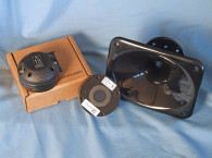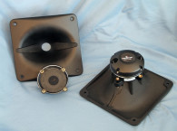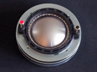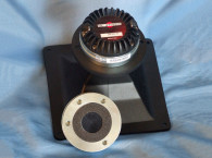

Other features for this compact design include a cast aluminum body, an 80 W AES-rated power handling (160 W program material maximum), a neodymium ring magnet motor, 110 dB sensitivity, minimum crossover frequency of 0.9 kHz, and color-coded push terminals. The horn supplied with the HF142 driver is FaitalPRO’s LTH142 injection-molded PC/ABS with a 1.4” throat. The LTH142 is a 60°H × 50°V elliptical Tractrix-type horn with a 9.5 dB directivity index.
I began the tests on the HF142 using the LinearX LMS analyzer to create a 200-point stepped sine wave impedance plot (see Figure 1). The solid black curve was obtained with the HF142 mounted on the LTH142 horn. The dashed blue curve represents the compression driver without the horn. With a 5.76 Ω DCR, the minimum impedance of the HF142/LTH142 was 7.57 Ω and at 5.41 kHz.


Next, I recess mounted the HF142/LTH142 combination without an enclosure in free air, then measured the horizontal and vertical on and off axis at 2.83 V/1 m using a 100-point gated sine wave sweep. Figure 2 displays the on-axis measurement of the HF142’s compression driver/horn combination. The response is approximately ±1.5 dB, 1 kHz to 13.2 kHz, followed by the low-pass roll-off. With the LTH142 horn’s coverage pattern at 60°H × 50°V, you wouldn’t expect much of a difference in the horizontal and vertical off-axis plots, which is indeed the case when comparing the horizontal orientation (see Figure 3) and the vertical orientation (see Figure 4). Plots with the off-axis normalized to the on-axis response for the horizontal and vertical axis measurements are shown in Figure 5 and Figure 6 with the CLIO Pocket analyzer polar plots (with 10° increments) shown in Figure 7 and Figure 8, respectively. Figure 9 gives the two-sample SPL comparison of the HF142/LTH142, showing both samples to be as closely matched in the relevant operating range.
For the remaining group of tests, I employed the Listen, Inc., AmpConnect ISC analyzer and 0.25” SCM microphone using SoundCheck 14 software to measure distortion and generate time-frequency plots. For the distortion measurement, I mounted the HF142/LTH142 combination in free air without a baffle (the same configuration used for the frequency response measurements) and used a pink noise stimulus to set the SPL to 104 dB at 1 m (1.33 V). I measured the distortion with the microphone placed 10 cm from the mouth of the horn. This produced the distortion curves shown in Figure 10.


I then used SoundCheck to get a 2.83 V/1 m impulse response for this driver and imported the data into Listen’s SoundMap Time /Frequency software (now integrated with SoundCheck 12 and up). Figure 11 shows the resulting cumulative spectral decay (CSD) waterfall plot. Figure 12 shows the Short Time Fourier Transform (STFT) plot. FaitalPRO’s HF142 is a beautifully crafted product with outstanding build quality and excellent performance.
For more information, visit www.faitalpro.com. VC


This article was originally published in Voice Coil, March 2017.


