

MISCO currently manufactures tweeters, woofers, subwoofers, and midrange drivers from 1” to 21” enclosures, single and multi-channel amplifiers (with or without DSP), plus turn-key products combining all of these items. Besides manufacturing, MISCO also provides some high-profile loudspeaker testing services. Some of the recent highlights of MISCO’s 70-year history include:
• 1990 — Dan Digre, Cliff’s son, takes over the company management as President of MISCO
• 2001 — MISCO builds a new, expanded engineering and manufacturing facility in Minnesota, adding amplifiers and complete audio systems to its product mix
• 2015 — MISCO acquires Warkwyn, one of the best-equipped independent audio test and measurement labs in North America, and moves the company from Canada to Minnesota. The synergy created with Warkwyn puts MISCO into a unique position to serve the industry with the best and most extensive loudspeaker design, testing, and manufacturing capabilities in North America. Notably, Warkwyn is also Klippel GmbH’s exclusive North American sales and support agent
• 2016 — MISCO acquires Oaktron from Mitek Corp. and moves it to Minnesota. This acquisition further expands MISCO’s commitment to US manufacturing and adds product offerings for the military, aerospace, and mass transit markets
• 2019 — MISCO launches a new brand, Bold North Audio, starting with the introduction of a direct replacement midwoofer, the MS10W, for the Yamaha NS10 studio monitor loudspeaker
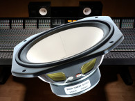
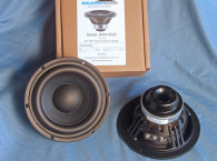
The subject of this month’s first driver Test Bench report is the new MISCO 6.5” MS-10W (see Photo 1), which is an extremely close replacement woofer for the legendary Yamaha NS-10 studio monitor. If you are not involved with the studio monitor sector of this industry, or do not know much about the recording studio market, the Yamaha NS-10 is probably the most beloved and cherished studio monitor in recording industry. The product was introduced in 1978 and continued in production until 2001, and the rumor is that more than 400,000 units were produced!
The MISCO MS-10W went through an extensive development cycle to ensure that it was as close a replacement woofer for the NS-10 studio monitor as possible. Given the number of years the Yamaha NS-10 was manufactured, along with the various incarnations of the product, coming up with a somewhat generalized replacement driver was necessary. To this end, MISCO has published a white paper explaining this rather interesting development of the MS-10W available on the MISCO Bold North website.
Features for the MS-10W include a lightweight white flat profile seamed paper cone (When was the last time you saw a seamed cone? Been a few hasn’t it!) with a paper convex dust cap, and a stamped steel frame with both front and rear mounting gaskets. There is no pole venting or venting below the spider mounting shelf. Compliance is provided by a 12 mm wide coated cloth surround and a 3.25” diameter cupped cloth spider (note the NS-10 was a sealed box speaker).
The motor assembly is powered by a 16 mm × 89 mm ferrite sandwiched between 5 mm front and back plates. Driving the cone assembly is a voice coil that consists of a 32 mm (1.25”) diameter paper former wound with a single layer of edge-wound copper wire. Voice coil tinsel lead wires terminate to a pair of solderable terminals.
I began testing with the driver rigidly clamped to a test fixture in free-air. Using the LinearX LMS analyzer and VIBox produced both voltage and admittance (current) curves at 0.3 V, 1 V, 3 V, 6 V, and 10 V. Surprisingly, the 6.5” MS-10W stayed linear enough for LEAP 5 Enclosure Shop to get a satisfactory curve fit, which is not always the case of 6.5” midwoofers. I post-processed the ten, 10-Hz-to-20-kHz 550-point stepped sine wave curve pairs for each sample and divided the voltage curves by the current curves, creating the five impedance curves. The impedance curves each had the LMS phase calculation procedure applied and along with the voltage curve for each sweep, imported them to the LEAP 5 Enclosure Shop Guide Curve library.
Since most Thiele-Small (T-S) data provided by OEM manufacturers is produced employing either a standard T-S model or the LinearX LEAP 4 TSL model, I additionally created a LEAP 4 TSL model using the 1 V free-air curves. Please note, that even though LinearX is no longer in business after the unfortunate passing of chief engineer and founder Chris Strahm, I will continue to use it until something that is as accurate at predicting high voltage excursion becomes available.
I selected the complete curve set, the multiple voltage impedance curves for the LTD model, and the 1 V impedance curves for the TSL model in the transducer derivation menu in LEAP 5 and created the T-S parameters for the computer box simulations. Figure 1 shows the 1 V free-air impedance curve. Table 1 compares the LEAP 5 LTD and TSL data and factory parameters for both MISCO MS-10W samples.
The T-S parameter (TSP) results for the MS10W were reasonably close to the factory data, with some variance in the Vas and Qe/Qt numbers. However, the Fs/Qt ratios are close and when the factory TSP box simulations were compared to my TSP box simulations, the F3s were identical. I then followed my standard protocol and preceded to program computer enclosure simulations, using the LEAP LTD parameters for Sample 1. To generate the first enclosures volume for the box simulations, I used the published sealed box volume of a Yamaha NS-10 for one of the simulations (634 in3). For the second enclosure simulation, I used the LEAP Quick Design utility, which specified a Butterworth Qtc = 0.7 sealed box alignment at 1 ft3 with 50% fiberglass fill material.
Figure 2 depicts the results for the MS-10W in the Yamaha NS-10 sealed box and a larger Qtc = 0.7 box at 2.83 V and at a voltage level sufficiently high enough to increase cone excursion to Xmax + 15% (4.4 mm for the MS10W). These calculations generated in a F3 frequency of 88 Hz (F6 = 73 Hz) with a Qtc = 0.97 for the NS-10-sized sealed enclosure and –3 dB = 69 Hz (F6 = 55 Hz) with a Qtc = 0.73 for the larger 1 ft3 box simulation.
Note the original NS-10 had a specified F3 of 69 Hz, various examples measured during MISCO’s research varied between 70 Hz and 90 Hz, with woofer Fs varying between 42 Hz and 69 Hz! Increasing the voltage input to both simulations until the maximum linear cone excursion was reached resulted in 110 dB at 24.5 V for the smaller NS-10-type sealed enclosure and 105.5 dB at 16 V input level for the larger sealed box. Figure 3 shows the 2.83 V group delay curves. Figure 4 shows the 24.5/16 V excursion curves.
Prior to detailing the Klippel DA-2 analyzer LSI (large signal data) curves, I need to discuss some recent changes in protocol for measuring large signal data. Voice Coil magazine first introduced Klippel transducer analysis beginning in the October 2003 issue. Over the years, there have been changes in the presentation, including the inclusion of the grey symmetry region (see Figure 5 for the definition of symmetry region for the Bl curves added to the Bl symmetry range and Kms symmetry range curves in the June 2006 issue of Voice Coil magazine.


Moving forward to 2018, Klippel has been involved in two new International Electrotechnical Commission (IEC) standards—IEC 62458 fdis ORIGINAL, and IEC 62459 draft (if you are interested, both standards are available on the IEC website at a cost of $140 for IEC 62458 and $100 for IEC 62459). These new standards call for the elimination of the KMS symmetry range curve in large signal measurements (specifically the Klippel LSI measurements), and instead recommend using a new figure of merit known as Stiffness Asymmetry AK, expressed as a percent (see Figure 6). A more detailed explanation of Stiffness Asymmetry AK is given in Figure 7 showing its mathematical derivation (note Figures 5-7 were supplied by Klippel GmbH, and are taken from the Klippel Sound Quality of Audio Systems seminar power point presentation). In terms of how to interpret AK, the number has a sign associated with it (±), and shows the soft nature of the compliance (a negative sign means the stiffness is softer for negative [coil-in] position). For example, a number greater than 20% would indicate that measurement of DC displacement is recommended. This new protocol is part of the new Klippel LSI 3 measurement software and will be the new standard used in all future Test Bench reports.
Klippel analysis for the MS-10W produced the Bl(X), Kms(X), and Bl symmetry range plot is given in Figures 8-10. However, since MISCO/Warkwyn is the US agent for Klippel GmbH, I asked them to supply the Klippel analysis for the MS-10W report.
The Bl(X) curve for the MS-10W (see Figure 8) is mostly symmetrical and moderately broad with a small amount of offset, but as you would expect for a moderate Xmax (3.85 mm) 6.5” driver. Looking at the Bl symmetry range plot (see Figure 9), this curve is offset a trivial 0.16 mm coil-out offset at the position of reasonable certainly (narrow region of the Bl curve) at 3 mm and increases only slightly to 0.28 mm coil-out offset at the driver’s physical 3.9 mm Xmax.


Figure 10 gives the Kms(X) curve. The Kms(X) curve is also very symmetrical, again with an extremely small amount of offset. The Akms number for this driver is a very small -0.60%, indicating a well-behaved compliance system. Displacement limiting numbers calculated by the Klippel analyzer for the MS-10W were XBl at 82% Bl = 4.18 mm and for XC at 75%, Cms minimum was 4.06 mm, which means that for the MS-10W, the compliance was the most limiting factor at the prescribed distortion level of 10%. However, both numbers exceed the 3.85 mm Xmax, and are nearly identical.
Figure 11 gives the inductance curves L(X) for the MS-10W. Inductance will typically increase in the rear direction from the zero rest position as the voice coil covers more pole area, which is what you see in the inductance graph. From Xmax out to Xmax in, the inductance range is only 0.45 mH to 0.87 mH, which is only a 0.42 mH delta.
Next, I used SoundCheck 16 software and the AudioConnect interface with the 1/4” SCM measurement microphone and set it up for distortion measurements (supplied courtesy of Listen, Inc.). I mounted the MS-10W in free-air and set the SPL at 1 m using a noise stimulus set to 94 dB (4.45 V), my standard for home hi-fi drivers, which includes studio monitors. The MISCO MS-10W produced the distortion curves shown in Figure 12.


Then, I mounted the MS-10W in an enclosure with a 12” × 8” baffle and took the impulse measurement. This was imported into Listen, Inc.’s SoundMap software, windowed to remove the room reflections, which produced the cumulative spectral decay (CSD) waterfall plot shown in Figure 13 and the Wigner-Ville plot shown in Figure 14.
For the remaining series of SPL measurements, I measured the driver frequency response using the Loudsoft FINE R+D analyzer and the GRAS 46BE microphone, on and off axis from 300 Hz to 20 kHz with a 1/6 octave smoothing (to simulate the 100-point LMS resolution used for years in this column) at 2.83 V/1 m, using the cosine windowed Fast Fourier Transform (FFT) method. Figure 15 depicts the MS-10W on-axis response, yielding a relatively smooth rising ±2 dB response from 300 Hz to 5.2 kHz without any significant breakup mode peaks. Figure 16 illustrates the on- and off-axis frequency response at 0°, 15°, 30°, and 45°. The -3 dB at 30° with respect to the on-axis curve occurs at 2 kHz, which incidentally was the crossover frequency of the Yamaha NS-10. Figure 17 shows the normalized version of Figure 16. Figure 18 shows the CLIO Pocket (courtesy of Audiomatica SRL) generated horizontal plane polar plot (in 10° increments with 1/3 octave smoothing applied). And last, Figure 19 gives the two-sample SPL comparisons for the MISCO MS-10W, showing both samples closely matched throughout the driver’s operating range, with a 1 to 2 dB variation above 2 kHz.


This driver represents one of the more historically interesting projects I’ve encountered in some time — that of creating a replacement driver the iconic Yamaha NS-10 studio monitor. Given the amount of research and care that Tom James and others at MISCO painstakingly went through, including conversations with the original Yamaha transducer designer, Akira Nakamura, I think the results speak for themselves. It seems the Yamaha NS-10 will now live on forever! VC
This article was originally published in Voice Coil, February 2019.


