I first started my audiophile journey 25 years ago. I had a friend who was buying fancy high-end gear and was never satisfied with what he got. I liked high-end music, but I decided that building my own gear based on DIY electrostatic panels was the way to go. I built five different models, until I started to search for a subwoofer that could match my electrostatic speakers.
The problem was that I needed a 400Hz crossover to match my 100cm × 50cm electrostatic panels. Commercial subs did not go that high so I tried several types of subwoofer concepts, including a couple of floor-to-ceiling transmission lines but they didn’t blended well with my panels. Eventually I decided that motion feedback (MFB) was the right way to go.
I designed a unique capacitive position sensor to feed my feedback loop and in those years—when the Internet was still young—I did actually think that MFB was another of my inventions.
I also had to solve some challenging issues of loop stability and noise but eventually it all worked fine, and my subwoofer project blended very well with the panels. I was very pleased with the results and I still have this setup working fine. I kept my MFB and sensor research going through all these years with a few types of position sensor concepts that were all too complicated or too noisy.
Home Studio Opportunity
In 2018, the idea for desktop subwoofers crossed my mind. During my work with Waves, I met quite a few sound engineers in small and home studios. They all loved their small monitors—claiming they were “extensions of their ears” and that they would never consider using other monitors. They did their mixing jobs without listening to really accurate base notes through their speakers. They all tried subwoofers at some point and rejected them because they did not blend well with their monitors and excited nasty room modes.
So I thought that if I could make subwoofers small enough to be placed under the monitors, that would be a good start. And if I could design the subs wideband enough, then I could get a perfect acoustic wave front blend at the listener’s ear height. By using a crossover higher than 100Hz, I could get rid of bass-midrange intermodulation in the monitors and drive them to higher SPL. And by using MFB, I could get wideband flat response down to 25Hz with small sealed enclosures. I could also get more benefits, such as fast transient decay, mitigation of driver parameter aging, and thermal compression. And with nearfield listening to the subs, the direct wave would dominate, mitigating room reflection effects.
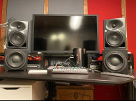
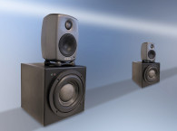
So I headed out on a more than two-year journey of designing and building several MFB subwoofer prototypes. This ended with my current version of desktop subwoofers, the ZRS-1 motion feedback desktop subwoofers shown in Photo 1, which I am now showing on my website and that I’ll explain.

Listening tests with professional sound engineers left them speechless, claiming they had not had such a listening experience. They also told me that home studios could be a huge market for such a product.
One of the most regarded sound engineers here in Israel (www.yuvalsound.com) had a session with these subs and the Neumann KH 120 monitors that he uses in his studio. He was so impressed by the sound quality enhancement that he keeps this setup for demonstrations in his studio, claiming that this concept is a paradigm shift. He helps me with his listening skills, contacts, and knowledge free of charge.
All that made me think that the desktop sub idea is worth commercializing. I do not have the financial means to invest in a manufacturing operation and it doesn’t make sense to me, with all the supply chain issues these days. My goal is to get into a technology licensing agreement with speaker manufacturers. Although I have no patent protection, I have quite a bit of knowledge, hands-on experience, and knowledge of the hardware needed for successful MFB implementation.
Other than the desktop subs I am also focusing on subs for automotive sound systems and for soundbars. There are not many audio engineers that know their way with MFB. It is an almost forgotten technology that I brought back based on current driver materials, MEMS accelerometers, and Class-D amplifiers that are the key MFB enablers of my design.
All that technology was not available in the 1970s and 1980s when MFB was a hot research topic. Any manufacturers would have to invest years with some talented engineers working to get to where my prototypes are today.
Bottom Line
I have no secrets or protected IP other than my know-how and the specific details of my circuit design. I can bring any speaker designer up to speed with any MFB subwoofer application using any driver and box size based on my power and control circuits. It is all hardware, no software or DSP — just old fashioned electronic circuits. But it works! Adding DSP features with room correction, smart crossover and Bluetooth (BT) connectivity, the design could also fit consumer products.
The Concept
Small studio monitor speakers are widely used at home and in professional studios. Most models are based on a two-way design with a 3” to 5” midbass driver in a ported enclosure and a tweeter. The midbass driver design parameters are selected to follow Thiele-Small or other design formulas and for a given enclosure size, excursion level is limited, restricting low-frequency production. When the maximum excursion level is exceeded, driver nonlinearity causes midrange modulation by the bass notes, compromising stereo image and clarity. Therefore, many small nearfield monitors roll off sharply and filter out the frequency range between 30Hz and 60Hz.
Even with careful design, a ported enclosure is resonant, yielding sustained, over hanged low frequency notes (resulting in boomy or boxy sound). Adding a floor-standing subwoofer to complement compact studio monitors with a low-end frequency range causes room mode excitation. Sometimes, even with careful placement, subwoofers do not blend well with studio monitors.
Small desktop subwoofers that can cover the 30Hz to 400Hz range can be used with a crossover at 100Hz or even up to 200Hz, thus relieving the monitors to produce only the midrange and high-frequency notes, basically forming a three-way configuration.
Perfect acoustic wave front alignment can be achieved at a listener’s ear height when the monitor speakers are placed on top of desktop subwoofers. And with nearfield subwoofers aimed directly at the listener, room reflection effects can be significantly tolerated.
A 20cm × 20cm × 20cm enclosure with a 6” long throw woofer seemed to be a practical design goal for a desktop subwoofer that can fit many types of studio monitors on top of them. Designing such a small subwoofer for powerful bass production is a significant challenge that can be met implementing motion control to mitigate the inherent resonances of such a small enclosure.
Overview of Commercially Available Subwoofers
Sealed or ported enclosures are the classic design concepts commonly used for subwoofers. Driver parameters have to be carefully selected for a given enclosure size following Thiele-Small (T-S) parameters or some Computer Aided Design (CAD) rules. The frequency response of a ported enclosure is resonant (a port is a Helmholtz resonator), yielding slow decay, sustained, over hanged bass notes (boomy, boxy bass).
Sealed enclosures are known to have better bass control than ported enclosures but larger enclosures and carefully selected drivers are required to get the bottom octave covered with acceptable transient response.
Large enclosures also require carefully designed bracing to mitigate panel vibration and driver parameters have to be well controlled in production and designed for long-term stability.
Thermal compression is another well-known issue with subwoofers. The voice coil temperature increases during regular operation and when it reaches 125°C, the copper winding resistance can increase to twice as much, reducing the power drawn from the amplifier by up to 6dB, thus compressing SPL and degrading transient response. Many commercial subwoofers get damaged with voice coil structural failures due to adhesive overheating, therefore, expensive over-rated drivers are often used. All these issues can be mitigated by using MFB control.
MFB for Bass Reproduction
Speakers using MFB have some sort of a sensor monitoring the voice coil’s movement. The sensor’s signal is fed back to the amplifier’s input through a control circuit and compared with the input signal. The error signal forces the voice movement to produce sound pressure that follows the input signal.
MFB technology for low-frequency speakers is not something new. For many years only a few manufacturers implemented this technology because of its design complexity and driver and amplifier limitations. But these are no longer considered an issue with current electronics and driver materials.
With MFB, driver specifications are no longer critical to satisfy T-S or other design rules because the sensor and control circuit take care of frequency response and resonance suppression.
Long throw voice coils with reduced force factor can be used for MFB with increased linearity and higher SPL without compromising sound quality. Frequency response can be made flat from 20Hz and up to the driver’s break-up mode, thus the crossover to the monitors can be set at 100Hz and up to 200Hz.
Also, relatively small enclosures can be used with MFB without compromising SPL and sound quality. With small enclosures, panel vibration is not an issue and bracing is not required. Thermal compression and harmonic distortion are reduced significantly with MFB due to the global negative feedback.
During the last 40 years, many methods were investigated for real-time sensing of voice coil dynamics. Phillips published a research paper in 1968 and manufactured several MFB bookshelf speaker models. Infinity, Velodyne, Sony, Yamaha, Grimm Audio, and other speaker manufacturers also used MFB successfully.
Optical, capacitive, inductive, Hall effect, sensor coil, accelerometer, ultrasonics and smart amplifiers were extensively experimented for voice coil motion control methods with limited success.
Many MFB-related patents were issued by private designers and by leading speaker manufacturers. Most of the MFB-related patents were abandoned, terminated, or expired after 20 years from their patent grant date and now can be used freely by the industry.
Current MEMS accelerometers technology, robust driver materials and availability of efficient, high power Class-D amplifiers, have changed the perception about MFB and enabled the design of affordable small subwoofers.
Proof-of-Concept Prototype Design
To implement my ideas and demonstrate the feasibility of a small nearfield desktop subwoofer, I chose to work with an accelerometer-based MFB. I designed an MFB control circuit, fourth-order Linkwitz-Riley crossover filters, switching power supply and a powerful Class-D amplifier, which I integrated into a 20cm × 20cm × 20cm MDF enclosure. I also modified a 6” long throw driver with the accelerometer bonded on the driver’s voice coil former.
Based on driver measurements and control theory, I decided to set MFB loop parameters for flat frequency response between 20Hz to 400Hz and I implemented a real-time voice coil temperature protection circuit, to keep the voice coil temperature below 125°C during overstressed operation. I also designed an overload monitoring circuit to sense the amplifier’s output voltage and switch on a red light when reaching close to the power supply rails.
A block diagram (Figure 1) shows the basic features of this prototype design. The subwoofer was designed to be used in a full-stereo configuration, but it can also be configured as a single subwoofer feeding two monitors with left and right low-frequencies summed.

ZRS-1 Concept Test Results
Six prototypes were built. All these prototypes yielded flat frequency response from 30Hz to 400Hz without any adjustments. Listening tests performed in untreated rooms showed that the subwoofer prototypes blended well with several brands of nearfield studio monitors, revealing the best of their midrange-high frequency performance with high SPL, superb clarity, and stereo image. Well-controlled powerful bass notes were experienced down to 30Hz.
Speaker acoustics theory teaches us that voice coil acceleration is closely proportional to the acoustic output of a woofer in a sealed enclosure (when in piston mode at low frequencies below breakup). With that in mind and having an accelerometer already mounted on the voice coil, measuring the accelerometer output was the easiest alternative for minimizing room reflection measurement errors.
The measurements (Figure 2) show the prototype’s accelerometer output with and without MFB. The first plot (green) shows the accelerometer signal measured with the feedback loop disabled. The second plot (red) shows the accelerometer signal with the MFB loop active. It is clear that without MFB a driver has a sharp resonant response. With MFB the response is flattened to 25Hz to 400Hz within ±1dB.

It is also known that at these low frequencies, very close microphone measurements on the driver’s acoustic axis are proportional to 1 meter distance measurements in an anechoic chamber or in free field. Figure 3 shows the 6” driver measured on the subwoofer’s acoustic axis with crossover filter bypassed (green), configured for 100Hz (red), and finally 200Hz (blue).

Conclusion
I demonstrated the feasibility of my ZRS-1 MFB small desktop subwoofers (Photo 2) that can be used to complement small studio monitors. Listening sessions performed with nearfield monitors placed on top of the desktop subwoofers demonstrated the mitigation of room reflection effects, enhanced SPL with superb clarity and stereo image. This MFB approach allows implementing subwoofers in compact enclosures, including for soundbars, car audio systems, and portable music devices.

I am open to cooperation through licensing, or any kind of business engagement with speaker manufacturers. aX
This article was originally published in audioXpress, September 2022.


