Multi-Layer Voice Coil Plate and Flat-Type Speaker Comprising the Same
Patent/Publication Number: US20180295451A1
Inventors: Min Dong Hoon (Gyeonggi-do, Korea); Kim Joo Bae; (Gyeonggi-do, Korea); and Kwon Soon Kwan; (Gyeonggi-do, Korea)
Assignee: ICUBES Co., Ltd., Gyeongi-do, Korea
Filed: April 28, 2016
Current CPC Class: H04R 9/06 20130101
Granted/Published: October 11, 2018
Publication of US10321237B2: June 11, 2019
Application granted: June 11, 2019
Number of Claims: 11
Number of Drawings: 6
Abstract from Patent
Disclosed is a multilayer voice coil plate capable of significantly reducing difficulties in designing and manufacturing a multilayer voice coil pattern, and a flat speaker including the same. The multilayer voice coil plate may include: a first-type voice coil pattern layer formed in the shape of a track and connected from a first outer via hole outside the track to an inner via hole disposed in the track; and a second-type voice coil pattern layer formed in the shape of a track and connected from a second outer via hole outside the track to an inner via hole disposed in the track. The plurality of first-type voice coil pattern layers and the plurality of second-type voice coil pattern layers may be stacked so as to be insulated from each other, and the first outer via holes, the second outer via holes and the inner via holes may be electrically connected through interlayer conductors, respectively.
Independent Claims
1. A multilayer voice coil plate comprising: a first-type voice coil pattern layer formed in the shape of a track and connected from a first outer via hole outside the track to an inner via hole disposed in the track; and a second-type voice coil pattern layer formed in the shape of a track and connected from a second outer via hole outside the track to an inner via hole disposed in the track, wherein the plurality of first-type voice coil pattern layers and the plurality of second-type voice coil pattern layers are stacked so as to be insulated from each other, and the first outer via holes, the second outer via holes and the inner via holes in the plurality of voice coil pattern layers are electrically connected through interlayer conductors, respectively, wherein the inner via holes of the plurality of first-type voice coil pattern layers and the inner via holes of the plurality of second-type voice coil pattern layers are vertically aligned at the same position, and electrically connected to each other through an interlayer conductor.
3. A multilayer voice coil plate comprising: a pair of base substrates facing each other; inner voice coil pattern layers formed on both surfaces of each of the pair of base substrates, respectively; insulating films covering the respective surfaces of the inner voice coil pattern layers on both surfaces of each of the pair of base substrates; and an outer voice coil pattern layer formed on each of the insulating films of outer surfaces of the pair of base substrates, with an adhesive layer interposed there between, wherein two insulating films on inner surfaces of the pair of base substrates, facing each other, are bonded to each other with an adhesive layer.
8. A flat speaker comprising: a multilayer voice coil plate; a vibration plate vertically coupled to an upper edge of the multilayer voice coil plate, and configured to vibrate in a direction parallel to the multilayer voice coil plate; a first input terminal installed adjacent to a first end of the multilayer voice coil plate; and a second input terminal installed adjacent to a second end of the multilayer voice coil plate, wherein the multilayer voice coil plate comprises: a first-type voice coil pattern layer formed in the shape of a track and connected from a first outer via hole outside the track to an inner via hole disposed in the track; and a second-type voice coil pattern layer formed in the shape of a track and connected from a second outer via hole outside the track to an inner via hole disposed in the track, wherein the plurality of first-type voice coil pattern layers and the plurality of second-type voice coil pattern layers are stacked so as to be insulated from each other, and the first outer via holes and the second outer via holes are electrically connected through interlayer conductors, respectively, wherein the inner via holes of the plurality of first-type voice coil pattern layers and the inner via holes of the plurality of second-type voice coil pattern layers are vertically aligned at the same position, and electrically connected to each other through an interlayer conductor.
10. A flat speaker comprising: a multilayer voice coil plate; a vibration plate vertically coupled to an upper edge of the multilayer voice coil plate, and configured to vibrate in a direction parallel to the multilayer voice coil plate; a first input terminal installed adjacent to a first end of the multilayer voice coil plate; and a second input terminal installed adjacent to a second end of the multilayer voice coil plate, wherein the multilayer voice coil plate comprises: a pair of base substrates facing each other; inner voice coil pattern layers formed on both surfaces of each of the pair of base substrates, respectively; insulating films covering the respective surfaces of the inner voice coil pattern layers on both surfaces of each of the pair of base substrates; and an outer voice coil pattern layer formed on the insulating film of each of outer surfaces of the pair of base substrates, with an adhesive layer interposed there between, wherein two insulating films of inner surfaces of the pair of base substrates, facing each other, are bonded to each other with an adhesive layer.
Reviewer Comments
Since the loudspeaker’s invention there has been a quest for the realization of a high-performance, one-way, full-range electrodynamic transducer. As with any loudspeaker system, controlling diaphragm behavior to meet the desired amplitude response, is a primary design criteria. Relating more specifically to the full-range transducer, the trade-off between adequate diaphragm surface area to achieve large signal requirements and small enough diaphragm dimension to provide desired wide-band amplitude behavior and dispersion has often resulted in a significant compromise.
One configuration that has been adopted for these devices has been that of the oblong or “racetrack” form factor. This allows for a narrower transducer width to provide good dispersion over a wide frequency range. A shortcoming with this design, when using conventional, concave cone structures, is that breakup modes over the long dimension can be problematic over a large portion of the passband.
A very high-performance version of this format was developed by Dr. Carl Pinfold of Merseyside Acoustic Developments in Liverpool, England, and first disclosed in the May 1983 issue of the British journal, Hi-Fi News & Record Review under the title, “One-way Drive.” The Pinfold device incorporated an elongated racetrack-shaped diaphragm formed from a block of balsa wood, driven by a racetrack-shaped voice coil interfacing with the diaphragm such that across the narrow width of the device, the undriven portions of the diaphragm were less than 20 mm.
While the units appeared to be handmade with rather poor unit-to-unit quality control, the best samples were impressive, setting a new standard for full-range transducer performance relative to smooth wide-band frequency response and wide dispersion. Inspired by the capabilities of the best samples of these devices, David Graebener (working with your trusty reviewer at our consulting firm, Solution Matrix, Inc. in the late 1980s) developed an advanced version of the Pinfold device, for Harman/JBL, with an even more refined balsa-based diaphragm driven by a multiplicity of elongated blade-shaped voice coils with only 5 mm of undriven diaphragm surface between the blades.
This high percentage of driven force-over-area combined with the well-behaved balsa diaphragm resulted in a very smooth response with little sign of breakup modes over the full range of the device (18 kHz). With the racetrack-shaped voice coil on the former blades, similar to modern, dual voice coil large Xmax woofers, the magnetic circuit provided rather substantial linear excursion capability, such that the large signal performance was also quite impressive. A key element in optimizing the performance of this type of device is the voice coil assembly and its interface to the diaphragm.
The patent under review discloses a new transducer with an elongated, flat diaphragm and associated voice coil assembly, similar in overall format to the transducer-type already described. The novelty of the new device is centered on the voice coil former structure coupled to the diaphragm.
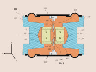
One goal of the new voice coil structure is to maximize the length of the coil in the magnetic gap while remaining within a target DC resistance. As can be seen in Figure 1, the flat speaker includes a voice coil plate 10 and diaphragm 20, which is coupled to the upper edge of the voice coil plate 10. The voice coil plate 10 has a multilayer structure including a first base substrate 110 and a plurality of track-shaped voice coil patterns stacked on both surfaces of the base substrate 110.


While this case appears to miss significant portions of the parts list, dimensions, and optimization information, one could find that by applying and refining some of the disclosed techniques the layered voice coil structure of the patent application could be one effective means to drive the diaphragm of this type of transducer. VC
This article was originally published in Voice Coil, January 2019