In this article, the problem of designing vented enclosures is revisited, with a backward concept: from the box to the driver as opposed to taking a given driver and designing an enclosure. The classical procedure starts by choosing a supposedly appropriate driver for the target enclosure. No specific recommendations are available for transducer selection, apart from designer’s expertise, which leads to a trial-and-error approach until a convenient transducer is found.
in contrast to this methodology, the backward approach starts by defining the system’s target performance, which can be defined in terms of physical volume VB (the smaller the better), lower cut-off frequency f3 (the lower, the better), ripple (the lower, the better), and maximum achievable SPL (the higher, the better). Having defined these target parameters (if feasible), the focus is put on finding candidate drivers that allow for such a design.
LoVE BASS has been developed to carry out this job in a quick and efficient manner, so that a substantial amount of engineering hours can be saved during the process of speaker box design.

LoVE BASS: An Open Tool for Speaker Selection
LoVE BASS is a tool developed for use in Matlab for the generation of vented enclosure woofer parameters. Given the target performance of the desired enclosure, two different approaches are considered. One approach searches for suitable drivers within a database. The other aims at defining the goal parameters to manufacture a custom driver. Either one approach or the other will be carried out by selecting its corresponding menu tab.
Selection of Suitable Drivers from Database
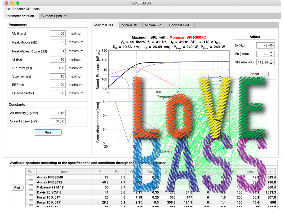
When running LoVE BASS, we are first required to input the goal performance parameters of the desired vented enclosure (see Figure 1). In addition, LoVE BASS allows the user to specify the estimated leakage quality factor QL, as well as setting some driver restrictions, such as the maximum allowed driver size and the minimum EBP value. LoVE BASS comes with a default speaker dataset that is read from an Excel file. Nevertheless, this can be easily customized by the end user by simply choosing another Excel file including their own driver models.
When the algorithm is running, it starts seeking for those drivers within the dataset that allow a design that fulfills the target parameters. The way it proceeds is based on the equivalent circuit of vented enclosures. For the sake of simplicity, QL includes the effect of all box losses (not only due to leakage, which is the dominant cause of the total loss factor, but also due to port and damping material). After taking a driver from the dataset, a sweep for a wide range of values for VB and fB is carried out.
For each tuning, the SPL curves corresponding to the cone, the port, and the joint radiation are computed at the maximal rating values of the driver (i.e., without exceeding either the program power, to avoid physical damage, or the maximum linear displacement Xmax, to avoid distortion over 10%). From the frequency response corresponding to total radiation, the lower cut-off frequency f3, the ripple, and the SPL are compared to the target enclosure parameters. In case that all of them are simultaneously satisfied for at least one tuning, the driver is then added to the selection of possible drivers. Otherwise, it is discarded.
This procedure is iteratively repeated for all drivers from the dataset. After the loop is finished, a complete table listing all suitable drivers (if any) is displayed, including Thiele-Small (T-S) parameters, f3, VB, SPL, fB, and recommended port dimensions, among others. Upon selecting a subset of those speakers, the SPL and cone displacement curves can be represented. Moreover, in order to facilitate the engineer’s choice, four different solutions are suggested, aiming at maximum SPL, minimum f3, minimum VB, and minimum port size, respectively.
Let us illustrate this approach with an example, considering the input values given in Figure 1 and the speaker dataset from the 2019 catalog of Beyma, including 81 low-frequency drivers (courtesy of Acustica Beyma). After running the approach, the following suitable drivers are selected: the 112LW30N8, the 112MC508, the 112MCS508, and the 112SMN8. Moreover, depending on the specific driver choice, box volume, fB, and applied power, different solutions are displayed for maximal SPL (124.5 dBSPL), minimal f3 (55 Hz), minimal volume (35 ltr) and minimum port size, as shown in Figure 2.


Definition of Parameters for Custom Driver Design
The approach for custom driver design can be carried out by opening the corresponding tab from the main window (see Figure 3). Besides VB, f3 and SPLmax, the electrical resistance RE and the driver size are also requested. With this procedure, instead of the ripple, the alignment is to be chosen between B4, QB3, and C4. If QB3 is selected, the B parameter is also required. On the other hand, if C4 is chosen, the ripple of the frequency response (R, measured in decibels) should be specified. The configuration for the different alignments is shown in Figure 4.
For a specific alignment, the linear parameters of the transducer are unique and can be computed from a closed-form solution (see the block diagram shown in Figure 5). The first step is to derive the coefficients that satisfy the transfer function for the desired alignment. From them and the estimation of the leakage quality factor QL, the well-known normalized linear coefficients a, q, and h can be obtained.


Subsequently, the driver’s required linear parameters (i.e., fs, QTS, QES, VAS, and h0) can be derived. We should mention that, in order to obtain QES, we should previously set QMS to some arbitrary value (in this application QMS = 4 is considered). At this point, the speaker size allows us to estimate the effective diameter and hence, SD. With respect to RE, this will only affect the Bl value (the larger the RE, the larger the Bl value). On another hand, the required power rating of the driver can be computed from the maximum achievable SPL and the driver’s efficiency. Moreover, the Helmholtz resonant frequency is obtained from h and fs.
With all these parameters, the cone displacement curve at maximal input power can be derived and, subsequently, the linear cone displacement Xmax. After the driver properties are determined, the SPL and cone displacement curves are shown, as well as a table with all driver parameters (see Figure 3).
LoVE BASS allows for a final check to alert for the feasibility of driver manufacturing. Up to four warnings may appear due to some of the following reasons: too low moving mass, too high Bl factor, excessively large Xmax, and/or too high Pe. Moreover, a number of possible solutions are suggested to overcome these problems (see Figure 6).

Conclusion
Choosing an appropriate transducer is a crucial step for enclosure designs, and LoVE BASS is a useful tool to guide driver selection for vented boxes. Using this approach provides the following benefits: 1) It allows users to reach a design that fulfills the target box parameters; 2) A large amount of engineering hours can be saved, so that the electroacoustic engineer can focus on other design aspects; 3) The manufacturing cost of the box can be adjust by selecting the most inexpensive transducer among those that satisfy the technical requirements; and 4) Unfeasible designs are identified in case that too demanding target parameters are input.
For more information about LoVE Bass, contact Francisco (Paco) Castells by email. VC
About the Authors
Francisco Castells is lecturer on Electroacoustics with the Master in Acoustic Engineering program, Universitat Politècnica de Valencia.
José Manuel Requena is a postgraduate student in the Master of Acoustic Engineering program at Universitat Politenica de Valencia.
This article was originally published in Voice Coil, July 2019.


