
I met Robert Munnig Schmidt at Grimm Audio when he was working on the company’s original Digital Motion Feedback subwoofer. Only much later did I discover that he was also part of the initial design team at ASML, the famous IC fab manufacturing equipment company founded in the Netherlands in 1984 (ASML originally stood for Advanced Semiconductor Materials Lithography). He joined ASML after several R&D jobs at Philips Research… but of course, I needed to ask him about his initial trajectory and how he arrived there.
Jan Didden (JD): How did it all start?
Robert Munnig Schmidt (RMS):
It’s been a convoluted road, but there’s a common thread. It started with me, as a kid, playing the flute in a band. A friend’s father happened to be a recording engineer with the famous Ariola brand. This guy built his own mixing console and amplifiers, and my friend and I used his older equipment for our hobby. We built tube amps, and I put so much time into it that I had to double one of my college years. But you really must get a diploma at some time, and I went to study at Delft University. People told me, if you are a guy who understands instantly how something mechanically works just by looking at it, you need to study mechanical engineering. But if you really like math, you should study electrical engineering. I wasn’t bad at math, but not a wizard, so I decided to study mechanical engineering and do electrical engineering as a hobby. And that really was the start of the theme for my life.
My graduation project was a portable medical infusion pump, driven by a voice coil. It is conceptually the same as you see in some Bulova Accutron watches, with a vibrating mechanical part. It worked beautifully at my graduation and was also a sign that next to designing mechatronics I also wanted to work with my hands. Which is logical since I really loved to play with coils and magnets in the audio area.
JD: And then it was time to get a job?
RMS: Hah! What seems unbelievable in this day and age: after graduation, nobody offered me a job, so I coasted on unemployment benefits. I met a professor in Delft, and he said, “Have you thought about Philips?” — “Don’t they just manufacture light bulbs?” I asked. Totally out of touch. But the professor dictated my CV and a letter to Philips’ HR, and I got invited and ended up in the famous NatLab in Eindhoven.
I got to work in the Optical group. This was around 1977. They had two major projects: optical recording and the Silicon Repeater, which turned out to be the precursor to what later would become ASML! Because of the strict hierarchical organization at the time, each employee would be attached to a university graduated person who he would report to. One guy, Gerard van Rosmalen, was attached to me. He was older than me and already famous as the designer of many patented designs of the motion systems that were used for the optical pickup of VLP and the compact disc.
I learned as much from him as I could. One important thing I learned was to have no fear of mass. He taught me that mass and bandwidth can be largely decoupled.
The wafer stage of the Silicon Repeater was hydraulically powered, and there were always leaks, stuff got oily, not a good idea in a CD cleanroom. I concluded we should be able to do that electronically, and if you must move more mass, you just use more power!
JD: But if the mass is higher, it is more difficult to get it moving—and stopping—fast. That must have bandwidth repercussions.
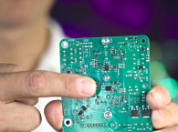
RMS: It can be controlled separately. If you have a large mass to move, say a thick heavy rod, it takes some time from the movement of the actuator until the effect reaches the end of the rod, there’s a wave traveling through the material. But it is still moving much faster than sound in air. If you actuate a heavy load with a big coil and magnet, it’s pretty easy to get sufficient bandwidth to control the accuracy (Photo 1). The real limit was amplifier power.

I was never a big fan of feedback, as feedback is a reaction to an error so is always late. Feedback doesn’t eliminate distortion, it can only decrease it, so it should only be used after you have done your best to make the amp as linear as possible! I thought, in a switching amp, the output switches between positive and negative supply so you wouldn’t have crossover distortion. And I really designed that switched stepper drive amp with audio in mind, for 20kHz bandwidth. But to my chagrin, that amp also had crossover distortion!
JD: In a switching amp there’s no gradual current takeover from one polarity to the other. So, what is the mechanism?
RMS: Depending on the current direction, the energy in the filter coil will try to keep the current flowing. As a result, a positive current will speed up the negative switching ramp from the input of the filter, while a negative current speeds up the positive ramp. At the crossover point, this causes a change in ramp speed and that manifested itself as crossover distortion. You can minimize it with circuit optimization and feedback after the low-pass filter—as Bruno Putzeys has done at Philips, and later at Hypex in the UcD amplifiers—but you can’t get rid of it completely.
Nevertheless, the amp worked fine in the stepper and was still used in the early ASML equipment. This was, however, a voltage amplifier, but nowadays everything in wafer steppers and the modern wafer scanners is current driven with current output amplifiers to guarantee a driving force that is only dependent on the current and no other factors like motion feedback and self-inductance.
JD: Did Philips have audio motional feedback products on the market at that time?
RMS: Yes, they did, and it was then that I found out that—for cost reasons—there was a big discrepancy between what the designers at Philips delivered and what was finally put out to the customer under the adage: “a bit better is good enough.”
I then contacted the factory in Dendermonde in Belgium and got some discarded motional feedback (MFB) drivers with intact sensors. I bought a pair of Isophon 12” woofers that had the magnet inside the voice coil, which I thought was a smart design. No stray fields. It was still ferrite, so the field wasn’t particularly strong. I mounted the salvaged sensors in the Isophones, connected to some control electronics I made from the last schematic from the NatLab audio guys. This was my first MFB speaker and I still use it today!
JD: So that launched you on the audio path?
RMS: Not yet! I had a good job at Philips but had no time for hobbies, so I had to buy my stuff from the Philips personnel shop. I bought a pair of Philips Digital Speakers, they sounded horrible. I made some improvements, but it remained a dud. I gradually became more and more disappointed about the role of technology at Philips under the pressure of cost-driven marketing, so I decided to move (back!) to ASML where my technical skills were challenged more.
JD: But you left ASML; why?
RMS: At one time I was asked by my alma mater, Delft University, for a professor post. The stress and workload at ASML had started to take its toll, so I thought, why not, even with a pay cut. I took the jump, only to find out that I did not easily fit in the role of a good university professor. But I had to adapt in many more ways. It takes years of hard work and study before you get to be a professor, but once you have your seat, you’re on your own. If you wanted to do some research, you had to find the money somewhere through mostly bureaucratic channels. And if there is one thing an ex-ASML director hates, it’s bureaucratic channels! The contrast is immense.
At Philips you only went to your boss when the project was finished, and you had solved all issues. “Don’t bother me with your problems.” At ASML, you were asked: “Did you finish the project? If not, what can I (as your supervisor) do so you can finish it? What do you need, do bother me with your problems, because that’s what I am here for!”
At the university, there was no common goal nor a demanding and supporting supervisor that I appeared to need for motivation. That was the motivation to write my book on mechatronic engineering [1].
JD: It doesn’t sound like you were happy at the university.
RMS: I loved teaching, but I hated examinations, and the research was not really satisfying as the work of one student per topic never goes fast enough when you are accustomed to the ASML environment.
I was saved when a student told me: “I want to work on motional feedback.” I thought, isn’t that old hat? We worked on that decades ago!
First, we would find out how the “plant” as we called it, worked, characterize all nonlinearities and resonances, and then tried to compensate for that. That’s feedforward control. Ninety-nine percent of the work at ASML is to make sure the hardware works very linearly before the application of feedback. If you have 100 kilograms of mass banging around at nanometer scales, and you want to linearize it with negative feedback, it’s a lost case, you get a bandwidth of maybe a few 100Hz if you’re lucky. So, we always put a lot of effort into mathematically describing the plant and linearizing it, and then adding negative feedback.
When we started on the design of a MFB loudspeaker we approached it the same way, starting with feedforward control. And that didn’t work. You can try to characterize the driver, and Wolfgang Klippel, for instance, has done important work on that, but a driver isn’t a driver. Unlike an ASML item, which is characterized down to the smallest detail, a driver is a mass product and no two are exactly the same. You could characterize each individual unit and tune it, but due to external influences like temperature and wear this should be repeated on a regular basis, which becomes very costly. So, your model is never accurate enough. And the complexity of resonances and break-up, it’s all three dimensional, you just can’t correct them at a single point where the voice coil is attached…
JD: So, back to traditional negative feedback then?
RMS: Yes, but with a twist: implementing the control loop in the digital domain.
We started some experiments with a professional d-Space digital controller, with many options and degrees of freedom. I got a few ACH-01 acceleration sensors, and we were having lots of fun. But ultimately, we needed a low-cost digital control that could be manufactured and implemented in every driver.
A DSP solution needs A-D and D-A conversion that in most converters causes delays of several milliseconds latency, which drastically lowers the stable control bandwidth you can achieve. The same problem exists for noise cancelling headphones, and we discovered that these use special A-D and D-A converters with latency down to a few microseconds! It’s not really hi-fi but we wanted to use it for the lower octaves only. You can make good tweeters, and as long as you stay away from the resonance frequency, a speaker can be very good. Speaker distortion is less irritating than amplifier distortion. At (very) low frequencies, however, you need to move a lot of air, so you need a large cone, which leads to a large enclosure, and you get a monster that nobody wants in the living room.
If you can reproduce down to 32Hz with full power and good linearity you can reproduce all music, even a 32’ organ pipe (16Hz), which mainly has the 32Hz harmonics anyway (Photo 2). But if you put a large cone in a small box, you get resonance frequencies at 50Hz or 60Hz and below that distortion rises very quickly and is very audible due to the fact that at the lowest frequencies our ears are more sensitive to the harmonics than to the fundamental.

JD: And the feedback will help you lower that distortion?
RMS: Yes, and with acceleration feedback you really add virtual mass to the system, which means lowering the resonance frequency. That is the basic effect of motional feedback. And to lower distortion you need loop gain. Where? Not at those frequencies at 32Hz, because the harmonics are above that! You need loop gain at 60Hz, 80Hz, 120Hz! Not many people realize that. And bandwidth is just a consequence of the loop gain you need at higher frequencies. We started to experiment with an ADAU1772 and later the ADAU1777, which had even lower latency, with onboard A-D, D-A and a DSP engine. That DSP makes the design so much easier. For instance, when you go up in frequency you get to the point where the surround dynamically uncouples itself from the cone. That means that the radiating surface and mass has a jump, which you see in the frequency response. If you wanted to correct that with feedback, you need more loop gain at that higher frequency, which means more bandwidth and stability issues. With DSP I can set a notch at that surround decoupling frequency, and don’t need loop gain there.
Another handy DSP function is a limiter, because when the system clips, the feedback only would make it worse. A bit of DSP limiting can prevent that.
JD: Did you commercialize that design in any way?
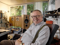
RMS: Well, at about that time, two things came together. One, I ran into my cousin Eelco Grimm and Guido Tent of Grimm Audio [2] who asked if I was interested in designing an MFB subwoofer for their LS1 speakers (Photo 3 and Photo 4). To put it on a commercial footing, I founded my company in 2012 and started to give courses on “Mechatronics Design” and the design of mechatronics-based audio systems. Eelco and Grimm Audio became my first customers for MFB.


There was one particular problem that was difficult to solve. Due to the forces on the cone at high levels and low frequencies, the sensor started to deform and generate output that disturbed the control system. That lead to the “Guido (Tent) bolt.” The sensor was mounted on a piece of carbon sheet attached to the cone. Guido’s idea was to put a small conical-head bolt into the carbon sheet and glue the sensor on the bolt head. That worked great! The coupling between sensor and cone was good and deforming forces on the cone were no longer transmitted to the sensor.
JD: What exactly do you want to sense, the voice coil movement or the cone movement?
RMS: Both really, it’s a matter of finding the best spot. And if you get to the frequency range where voice coil movement and cone movement start to decouple, you shouldn’t use it anyway. That’s the upper frequency limit where it can be used. But generally, it is best to mount the sensor as close as possible to the voice coil.
The early models I developed for Grimm had two bridged 400W UcD amplifiers with one 400W power supply. I finished two prototypes a month ahead of the Munich High End show. So we went to Munich, and it sounded all great, but at that show demos are always very loud. We tried to match that, and then intermittently we got silence as the power supply overloaded and had to be unplugged from the mains to be reset.
These prototypes were already current driven to avoid the distortion due to eddy currents in the magnet core and maximize the peak at the resonance frequency for higher loop gain. Because of the bridge configuration however, we needed a special IC to sense the current through a series resistor floating from ground. Unfortunately, that caused a lot of noise, requiring a too large sense resistor value. It would have to be a small resistor to avoid power loss; but this amplification needs to add as little noise as possible.
JD: Why is that noise such an issue? It’s all low-level control, isn’t it?
RMS: Noise is a real issue in motional feedback because it cannot be attenuated by volume control! You have to compete with amplifiers with 130dB dynamic range. With MFB the sensor determines the sound and its noise creeps into the control loop and ultimately into the drive signal. In production we settled on a single 700W Ncore amplifier with a 1200W power supply and a small sense resistor to ground, followed by a very low noise op-amp.
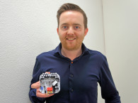
Now we get to the final act, the sensor. The ACH-01 still bothered me. I got a batch where some were pressure sensitive and reacted to the pressure inside the enclosure. At that point in time, I was actively involved in discussions on MFB in Hans Mons’ forum MFBLabs.nl. It was there that Chris Camphuisen from Piratelogic.nl discovered acceleration sensors as used in Murata hard disks [3]. These are very small sensors, manufactured with MEMS technology in small SMD form factor (Photo 5).

In the end I decided to manufacture my own sensors, using four of those MEMS parts in parallel to get a better noise figure, in a charge amplifier setup. And these are so good that it doesn’t really matter at what orientation they are mounted, which makes modification of a woofer much simpler: One can even glue the sensor at the back of the cone, close to the voice coil, and that’s it (Photo 6)! The connection cable is very supple to avoid mechanical interference. As you see the sensor assembly is electrically shielded because of the high impedance capacitive nature of the sensor elements.

RMS: Yes, and I give them a hand. It is still in the early stages; I don’t know when or in what shape it will materialize.
JD: What about the stability of MFB systems? Some designers seem to struggle with the idea for that reason.
RMS: In the past, the main problem with MFB systems was that they could become unstable over time when driver parameters change. That is no longer an issue. In a competent design, the phase and amplitude margins in the feedback loop can be made sufficiently large there’s never going to be a problem. I have systems here with 25-year-old sensors that play absolutely flawlessly.
JD: On your website, you are quite critical about bass reflex enclosures. What’s your take on that?
RMS: You know there’s something strange going on in audio. We talk about frequency response, but that doesn’t exist! It’s a mathematical translation of the time domain response through techniques like Fast Fourier transformation. ASML’s Martin van den Brink always called us “the Hertz mafia.” Without mathematics, a frequency response can only be constructed by using a continuous sinusoidal signal (time domain!), then wait until everything is stabilized, write down the response, then change the period of the signal, again record the response, and so on. You then construct a response graph with the magnitude on the vertical axis and the inverse of the period on the horizontal axis, which is defined as the frequency of the signal, by connecting all the dots of those individual measurements. With mathematics, we can calculate how it looks even from noise or impulse responses. And then we think that if we have a flat frequency response, all is well. But look at a waterfall plot; if all was level, the response would be bounded by straight lines, but that’s never the case! There’s always ridges, peaks and throughs.
And that brings me to the bass reflex enclosure. A bass reflex enclosure causes (at a certain frequency) the cone to come to a standstill while the resonance in the reflex tube causes acoustic output. That is, however, a static situation. In reality, if you start a signal, the first thing that happens is that the cone starts to move with a very large excursion because there’s no air resistance! Then the air starts to move, and the reflex tube starts to absorb energy and gets going, and eventually the cone comes to a standstill. When the signal dies out, the cone starts to move again and the cone and resonator both move, and you get oscillating air streams and ringing. With resonating systems, you store energy in mass, and that energy has to be released. You should listen to Victor Wooten & Marcus Miller’s “Miller Time” on Live in America over an MFB system: you hear the strong, dry transients beautifully. Play it over a bass reflex and the sharpness of the transients is gone. Bass reflex is a principally wrong concept.
JD: You are what we would call a purist.
RMS: Everything should be measurable, and there are still factors we don’t know yet how to measure. It reminds me of the discussion you had with Jan Lohstroh [4]. At the time, we hadn’t discovered transient intermodulation distortion in audio but we knew “something” was going on; by measuring and testing we develop methods to quantify it.
JD: You see a trend to much better designed and manufactured drivers like from Purifi, which have much less parameter spread between units, so they can be characterized more accurately. Is there a future where you design MFB systems based on feedforward techniques?
RMS: If possible, yes, it would seem to be less costly than to turn a woofer into an MFB woofer. Then again, those Purifi drivers aren’t cheap. It’s a choice between a $200 driver with a $100 MFB sensor system, or a $500 driver with feedforward. So, it’s not a clean-cut situation.
It is often suggested to use a real MEMS sensor for MFB as used in smartphones and such. They are cheap, include electronics and work from DC up to sufficiently high frequencies. Unfortunately, their sensor noise is still not solved, especially at higher frequencies. That’s the advantage of a capacitive piezo sensor, where the noise rolls off with frequency.
If you work with smaller speakers, the cone displacement for the same SPL is larger, which means that the signal-to-noise ratio of a MEMS sensor might be just OK. But with large diameter subwoofers, sensor noise still remains an issue.
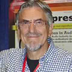
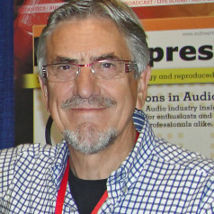
JD: Professor Munnig Schmidt (Photo 7), thank you very much for your time and the fascinating insight in motional feedback. I’m sure we will hear a lot more about it!
RMS: You can be sure about that. And thank you for the chance to talk about it! aX
References
[1] R. Munnig Schmidt, G. Schitter, A. Rankers, J. Van Eijk, The Design of High Performance Mechatronics - 3rd Revised Edition: High-Tech Functionality by Multidisciplinary System Integration, IOS Press, February 2020.
[2] J. Didden, “Grimm Audio: Building the Dream,” audioXpress, July 2023.
[3] MFB fora on the https://mfblabs.nl/forum (in Dutch).
[4] J. Didden, “An Afternoon with Jan Lohstroh,” Linear Audio, November/December 2009, https://linearaudio.net/sites/linearaudio.net/files/2022-12/An%20afternoon%20with%20Jan%20Lohstroh.pdf
RMS Acoustics & Mechatronics (https://rmsacoustics.nl).
This article was originally published in audioXpress, January 2024.