Extremely successful as an in-vehicle communication system, Analog Devices is increasingly supporting other audio use-cases. When I asked Duncan Bosworth, Analog Devices’ VP of Consumer, where he sees growing traction for A2B technology, this is what he had to say: “We are seeing expanded use of A²B in professional audio and conferencing applications. Our latest AD2437 transceiver incorporates a number of new features that enable a range of additional use-cases including digital musical instruments, MIDI devices, mixing consoles, and synthesizers/effects pedals. Manufacturers needing cost-effective, ultra-low deterministic latency and high-channel count audio transport can benefit from this A²B transceiver. Higher bus power, increased distance, SPI data transfer, simple plug-and-play discovery, and additional industry standard connector options are among the many improvements we’ve made. These upgrades will make a tangible impact in the future of the audio market.”
Last month, Part 1 ended with a look at the new CFG4 power system that provides 24V at 50W over twisted pair, favored for automotive applications. Now we’ll examine two alternative CFG4 power schemes that allow use of two common connector/cable types found in audio facilities: XLR and RJ45.
Other CFG4 Power Systems
For non-automotive applications, Analog Devices provides reference designs using two different power schemes based on the use of two different connectors: XLR and RJ45.
Analog Devices’ XLR bus power system operates on a similar concept as that used with powered microphones. Positive 24V is placed on the XLR’s positive (pin 2) and negative (pin 3) pins, and the return line (ground; pin 1) is connected to 0V (i.e., the power supply ground).
Since XLR cables could be mixed up between analog audio, AES/EBU digital, and A2B, there is a protocol for validating that the downstream connection is an A2B node that can accept 24V. With phantom-powered microphones +48V is fed through high-value 6.81K resistors, which even when shorted, limits current to 14mA. A2B’s 2A current limit is hefty enough to release the magic smoke from a non A2B device accidentally plugged in downstream.
The complexity comes because enough power must be supplied to enable the downstream AD2437 device to operate so that the upstream device can confirm it’s connected to another A2B device. 5V is supplied for that purpose by the upstream device. Analog Devices’ XLR reference design sets the 5V current limit at 100mA; about 30mA is needed to operate the node and read an external (to the AD2437) EEPROM that holds the node configuration information.
Figure 6 shows a simplified version of how 5V and 24V are supplied from the main node to a downstream node. The regulator on the output side supplies the 5V needed to provide the subordinate node power, allowing it to communicate with the upstream device to verify the sub-node can handle the 24V bus power. If a downstream (subordinate) node is locally powered, then it would look like the main node for how it supplies downstream power.

As with the previous A2B devices, the AD2437 has extensive line diagnostics to help determine if the node-to-node connection is open, shorted, or otherwise miswired. This can be a great help in figuring out why a setup isn’t working as expected; if there’s a reader here who hasn’t had to fix an XLR cable please step forward for your prize.
The XLR cable should be a DMX cable as proper operation of the A2B bus requires a controlled impedance cable with the + and – wires twisted to reduce noise pickup. The impedance of DMX cable is 120Ω; ideally A2B connections are done with 100Ω impedance cable but the difference is not enough to cause problems.
Figure 7 shows the RJ45 scheme, which takes a different approach and uses six of the eight wires for power. The two data lines carry 5V in a bus power scheme like the two-wire one. The 5V is used to power the downstream A2B device to confirm the cable is plugged in to another A2B device and not some other thing that uses RJ45 connectors and that might be damaged if 24V were applied to it. The AD2437 manages the 24V power so it can sense a short condition. As with the XLR scheme, sensing a short on the data line pair must be done by the device supplying the 5V.

No Free Lunch
For all three CFG4 power schemes consideration must be given to the connector’s ability to handle 2A as well as IR drop from the cable. DMX cable is suggested for A2B use as it has some semblance of impedance control versus audio XLR cable.
22 AWG multistranded wire is typically used and 2A is at the suggested current limit in terms of safe current capacity. With a resistance of 52Ω/km, a long internode 30m 22 AWG cable would have a resistance of 1.5Ω. Since two wires carry the positive power, the resistance is half that, or a voltage drop with 2A of 1.5V. The return wire will have a voltage of 3V across it. Since this is nominally the ground (shell/case) of the downstream device, bus powered nodes can end up not quite at ground (0V) potential; varying load currents could create noise on the ground connection, which would be a concern if the bus powered node connected to other equipment was referenced to an AC mains earth ground.
With the A2B two-wire bus power, both the positive and the return leg are connected through series pass transistors and current sense resistors to allow control and measurement of bus power. As with the AD2428 CFG0 power, downstream bus powered nodes cannot have any connection to other grounds as the upstream node will sense the current imbalance and assume a short or open in the wiring. The XLR scheme does not have sensing or control over the return current path.
Using three Analog Devices eval boards with two 25’ (7.5m) DMX cables, the measured resistance between the main (root) node and last sub-node PCB ground plane (i.e., two cables, four XLR connections) was about 600mΩ. This is actually less than the theoretical 750mΩ for 50’ of 22 AWG stranded wire. If this was extended to 10 nodes, then the last node is looking at 3Ω in the return path. Even with just a few hundred milliamps (mA) of bus power use, the local ground potential of the last sub-node is going to be significantly higher than the root node.
The other significant design concern with the AD2437 is that its jitter performance is the same as earlier generation devices, except since more nodes are supported, the jitter (Time Interval Error) at the end of the chain is in the 2.5nsec to 4.5nsec range. The impact of this type of jitter on audio signal quality is difficult to predict as A/D and D/A devices generally have some internal phase-locked loops (PLLs) that could ameliorate the worst effects of such high jitter.
Previously, Clockworks Signal Processing measured two different A/D and D/A devices and found that THD+N performance can be degraded considerably (more than 10dB)—the two studies are available on the Clockworks website. Most of that degradation comes from an increase in the noise floor, THD does not change significantly. In the case of an AK4619, a mid-range part, the A/D performance dropped from -96.3dB in its EVM (i.e., a local oscillator clock) to -94.4dB at the ninth A2B sub-node. The D/A section dropped from -99.3dB to -90.4dB.
More telling were measurements of the higher-performance AK4490 DAC, where THD+N performance goes from -109dB down to -96dB at the ninth A2B sub-node. Noise floor and dynamic range also drop, but by less than 1dB. Unfortunately, the poor jitter performance of the A2B parts seems to be an overlooked side effect of the way the main (root) node first synthesizes the 50MHz clock that runs the A2B bus as jitter performance of the first sub-node is already bad; about half the total at the last node. From prior experiments, it appears that the bus clock is synthesized from the main node frame sync input of 48kHz, which requires the PLL output to be 1024× the input clock rate. For sub-nodes, the problem is further compounded by A2B activity that is in a single burst, and when not many channels are being sent most of the time the A2B bus is idle, and the nodes need to free run for a significant portion of the sample (frame) period.
For playback systems the increase in THD+N, given it’s the noise being elevated vs. increased or more harmonics, is probably not audible as typical musical content will mask the noise. For a studio recording system, increased noise might be problematic. There’s also the bigger question of the reasoning to use high-quality A/D and D/A if A2B degrades them. It could be the case that the chosen A/D or D/A converters aren’t affected by the jitter, and this is a non-issue.
There are two relatively simple solutions where the application requires that the performance of the A/D or D/A needs to be preserved. One is to add an ASRC to the system so that the A/D and D/A are clocked from a local crystal oscillator, and the other is to add a clock clean-up chip and a simple bit buffer to reclock the data.
Getting Started
At the time of writing, AD2437 evaluation and development boards are available from Analog Devices and Clockworks Signal Processing. The Analog Devices’ boards come in two versions, a main (root) node and a bus powered sub node. There are in turn two versions of each of those, one with the XLR CFG4 power and the other with RJ45 CFG4 power. Also needed for development is Analog Devices’ USBi interface that allows the SigmaStudio+ tool to interact with the main (root) node’s AD2437 over I2C for control.
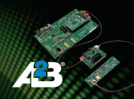
Photo 1 shows several development boards and how they might be interconnected. The main (root) node is Analog Devices’ EVAL-AD2437A1NZ board that can be a main or sub-node. The first node is Analog Devices’ EVAL-AD2437B1NZ board that is a bus powered sub-node that includes a stereo audio amplifier for driving speakers. The two nodes are connected with a DMX cable to provide data and 24V to power the first sub-node.

Sub-node 2 uses an AD2437 module with the 2-pin connector; since this is coming from an upstream XLR connection, the bus power is ignored as there’s no return connection. The node is locally powered. Since it’s designed to work with CFG4 power, there’s no special consideration needed for interconnect.
Sub-node 3 is the same Clockworks EVM board but with an AD2428 module. This module could be damaged if 24V was applied to its upstream port. Normally with the bus power scheme, the 24V on both signal wires would be ignored as a large common mode voltage. It’s not unreasonable that there may be a common ground in the system via the analog audio I/O, and if one A2B wire was disconnected then 24V could appear as a differential signal and do damage.
To prevent that potential for damage, a high-frequency pulse transformer is added to isolate the two different power domains (i.e., 24V CG4 of the AD2437 and the 9V CFG0 of the AD2428). The board shown in Photo 1 is a prototype of an upcoming Clockworks accessory so that you don’t need to build your own.
The transformer will have some loss and for maximal length inter-node cabling that might be an issue. Transformers are also very good at eliminating common mode noise and long cables are more likely to experience that. Different use cases will have different environmental factors and there’s no substitute for taking some boards out in the field with the intended cabling and see what, if any, issues arise. To further illustrate the flexibility of A2B, one more node is added — a Clockworks four-channel microphone board that is bus powered using the CFG0 rules (9V, 300mW).
In the automotive industry EMI/RFI is a major consideration for electronics, with most systems there needing better performance than typical FCC/CE requirements. A2B was designed with those requirements in mind, but actual performance depends on a lot of things that are outside of the chip itself. Enclosures, cabling, and grounding must be considered, particularly if nodes are going to be strung across large spaces. Quick prototyping and bench-type EMI tests should be planned in from the start.
SigmaStudio+
Analog Devices released a new version of its DSP design/programming tool. For AD2437 applications this is the version that must be used. SigmaStudio+ (SS+) by default creates a level of hierarchy for A2B applications where each block in the diagram represents a node as shown in Figure 8. In this view, the PC with SS+ is being used to control the A2B network over I2C. Audio is being provided to the nodes as analog input and output, or in the specific case of Analog Devices’ 2437B1NZ board used as the two sub-nodes, via stereo line input and output, stereo speaker output (20W/channel), and a PDM mic.

Figure 9 shows using SS+ to make the internal interconnections of one of the EVM (sub-node) boards. Some of what one would consider standard features in a graphical design capture tool are not available yet. Analog Devices is continuing development (a new version came out while this article was being written) and will hopefully continue making improvements to aid developers.

If a network node has programmable devices, the host can also load code to that; with the SPI connection in the AD2437, this is a reasonable option. The fastest network boot time would have all nodes running locally stored software and the sending code over the A2B network would just be used for remote update. With almost all microprocessors supporting a USB interface, it may be simpler to have users update firmware directly into the node than try that over A2B.
The firmware update issue is a lead-in to a much more undecided question about A2B, and that is if there will be any sort of minimal cross-vendor compatibility. Several ideas have been discussed to use the node’s local EEPROM for more than just CFG4 power compatibility status (i.e., the node could identify how many inputs and outputs it has, sample rate support, and maybe features, such as gain control). At the moment, it looks like A2B use will remain a vendor-proprietary system, though there’s always the possibility to make some sort of bridging sub-node.
Embedded Software
Analog Devices provides a basic driver that can be ported onto a microprocessor as well as a Linux one for larger systems. This driver can parse the output from SigmaStudio+ and load the network configuration as well as monitor for errors. Support for multiple configurations is included, but these are all predefined in SigmaStudio+. For fixed configurations of hardware, such as vehicle cabins, this provides for a reasonably simple integration path.
For the AD2437 and more generic audio installations, there will generally be too many combinations of hardware to have predefined configurations. There might also be applications where the hardware may be fixed but the routing of audio needs to be changed. A2B can send audio between nodes just as well as it can send audio back to or come from the main (root) node. As mentioned in Part 1, the AD2437 has a full crossbar for routing audio between A2B slots and I2S/TDM slots. This allows for some very sophisticated system configurations.
At the time of writing, there’s no direct support in the Analog Devices driver software for handling dynamic A2B routing nor crossbar management. Analog Devices has stated that it is working on it, along with defining the contents of a local EEPROM in a standard method so that a system can discover specific node capability.
For now, designers will need to develop their own software to perform the specific functions needed in their product. For applications where all nodes send/receive from the main (root) and the I2S crossbar is left in a fixed configuration, this is not a difficult task.
A2B Compared to Dante
Being Ethernet based, Audinate’s Dante standard can transfer audio data over long distances (fiber connections can range from a few hundred meters to tens of kilometers) within a large facility/campus. It can carry more channels than A2B (128 vs. 32). Dante’s relatively long audio delay (5msec is a reasonable allowance) vs. 50µsec for A2B make it less desirable for use within a single location, particularly where live sound is being used or recorded. Dante is a considerably more expensive solution than A2B and typically would not be found in a US $99 retail audio product.
Think of Dante as a complement to A2B; it can handle high-channel-count, long-distance audio very effectively. A2B provides a low-cost system with very low/fixed latency within a local area. Local here being perhaps a 50m × 50m space. There are demonstrated designs from two companies (Elytone and Fiberdyne) for bridging between Dante and A2B. For product developers, interfacing Dante to A2B is actually very simple in terms of data movement; it’s just I2S on both sides and using a part like Analog Devices’ ADAU1452 SigmaDSP in the middle solves the clock domain/sample rate matching issues. The complexity comes from allowing control of things from one side to another, particularly if the A2B devices are to appear unified under the Audinate tool set.
In the Real World
A2B is found in many automotive vehicles but its uptake in non-vehicle applications has by comparison been slower. Until recently, Analog Devices focused on automotive, and prior to the AD2437, the cable length limitations kept it out of contention for some applications.
In addition to the longer cable length, the AD2437 now supports faster A2B reconfiguration to handle nodes being added or removed while the system is operating — something that does not happen in car cabins. Factoring in typical product development cycles, it’s understandable that audio products with AD2437 won’t begin shipping until later in 2024. In the meantime, we can look at two A2B products that are shipping to see what might be next.
One is the BOSS (Roland) GK-5 divided guitar pickup that uses their digital Serial GK interface (e.g., A2B) to send each of the six pickup signals out as a digital value over a 1/4” TRS jack/cable to their base unit for processing. Bus power is provided from the base unit to the guitar end over the same cable that carries the A2B data.
In the BOSS application, A2B is being used in a point-to-point connection to keep the cable between the guitar and the base unit simple; an analog cable would need six pairs of wires and be well shielded. The second example is the Stage Connect product line from Midas/Klark Teknik (owned by Behringer/Music Tribe).


The DN4816 provides a USB bridge to a host computer, internally there is an XMOS chip to perform that function, along with a FPGA like in the DN4888 to handle the I2S routing. Interestingly, this box can be a sub-node, with the upstream node being other units. For example, the manual shows a console as the main (root) node. This starts to present some interesting issues for clock domains as the A2B main node always defines the I2S clock for the rest of the A2B nodes; when bridged over USB to a Windows PC, strange things can happen from the mismatched clocks if the audio data is routed through Windows instead of straight to the application.
A simple graphical app is supplied with the units to select which of the (current) four models is being used and their interconnect order. Currently, StageConnect devices route all audio to/from the main node, which is assumed to be a PC/DAW or a mixing console so there’s not any real need for other audio routing.
In Summary
There is both flexibility and complexity under the hood for A2B, but we hope this article series has conveyed the basics to get you started with A2B. It has truly unique capabilities for digital audio movement, providing better performance at a lower cost than the alternatives that have preceded it. aX
Read the first article: A2B Audio Bus: Ten Years and Three Generations
Resources
Analog Devices’ main A2B web page provides links to part information, Analog Devices tools, and related design information, www.analog.com/en/applications/technology/a2b-audio-bus.html
Clockworks Signal Processing, https://clk.works
This article was originally published in audioXpress, August 2024


