Today, electric motors are required to operate within an optimal rpm range and, for that reason, are equipped with frequency inverters. LED lights with switch mode power supplies are replacing incandescent bulbs. These are just two examples that showcase the present day trend for increased efficiency and better controllability through the use of the switched mode controls.
Regardless of the positive benefits in terms of increased efficiency, these circuits can also lead to increased interferences, which often go unaddressed to date, although they are now becoming more relevant. The topic of overlooked interferences concerns that of high-frequency interferences on the ground as well. The ground receives little attention, compared to interferences generated on the line, during the EMC-compliant design of electronic devices. Yet, this can quickly change if a ground loop develops.


Ground loops develop due to the different impedances of various ground connections from one or more devices. While all ground connections have the same potential for the 50Hz load current, they can have different potentials due to the different line impedances for the high frequency interferences. As a result, switched mode circuits have high frequency currents that can be transferred by the capacitive coupling or via interference suppression capacitors to the ground. There is usually no problem if the ground is good or there is only one ground connection; these currents are conducted to the ground. But, if there are different potentials from two or more ground connections, this can produce high frequency currents.
The effects of the equalizing currents on the ground can be drastic: for example, the interferences may damage the electronic control of the device. It is also conceivable that this can result in failure to meet EMC specifications, even though a suitable filter was installed in the device.
The problem can be solved by adding a ground choke. The ground choke, however, must be correctly specified in order for it to also satisfy strict safety regulations, with regard to conductor cross section and resistance. Furthermore, the ground choke must be installed so that possible high frequency interference currents on the ground cannot circumvent the choke via the housing. This is particularly a concern with in line filters. These filters are screwed directly to the metal housing for optimal performance. By screwing the filter casing directly to the grounded metal housing, low impedance is achieved, which thereby improves the interference suppression capacitor’s damping properties to ground. Device inlet filters or installed filters that are connected this way, to the mounting flange on the metal housing, are thus connected directly to ground. In addition, they also have a ground connection that is connected via a cable to the housing. If a ground choke is now integrated into the ground cable after the filter, the interference currents can bypass the choke via the metal housing of the device and the filter housing.


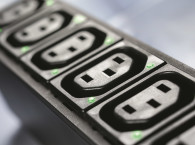
Schurter offers a simple and safe solution to solving ground loop interference with its KFA power entry module, which integrates a ground choke. In addition to the current compensated choke on the polar and neutral conductors, the mains filter has another linear choke on the ground conductor. This ground choke isolates the metal housing and the ground connection of the device from the mains ground. This solution effectively breaks any possible ground loops. The KFA power entry module with 1- or 2-pole fuse holder and filter is available in a wide range of versions and models. The filter with the ground choke also meets current safety requirements.
www.schurter.com
Article provided by Schurter - Diane Cupples


