Past articles in Speaker Builder and audioXpress have dealt with the issue. This article shows examples of diffraction and a commonly used, yet inexpensive, method to control it.
The Problem
Cabinet edge diffraction, which is unavoidable, is the result of any obstruction or cabinet boundary (edge) that changes how the sound wave moves across the surface of the baffle. Obstructions are primarily other drivers (midranges or woofers) and baffle edges and protrusions. These latter have been of more interest to me recently as I now prefer a baffle that offsets the drivers (a “stepped” baffle) to attain a better phase relationship between drivers in order to improve the crossover design.
The results of attempts at diffraction control were a bit surprising.
A sound wave will diffract when it encounters one of the obstructions mentioned.
This causes interference with the main sound wave that is traveling outward toward the listener. This interference is delayed in time from the main sound wave and is a function of the distance to the diffracting obstruction (such as the baffle edge). It arrives at the listener position, altering the perception of the sound, since its arrival is close enough in time that you perceive it as being part of the main sound wave.
Delays that are longer (such as reflections from walls) are perceived differently and are not confused with direct sound.
You’re familiar with this latter aspect of reflections. Box placement and room treatment are used to control that to a degree. The diffraction can’t be controlled by any kind of box placement or room treatment. You would somehow like to stop the diffraction from any obstructions, but how?


The Solution
More than one way exists to deal with diffraction. You can mount drivers with an offset from the centerline (useful on its own), but this only changes the distribution in the time and frequency domains; it doesn’t actually reduce the amount of energy re-radiated. Another way is to round over the baffle edge. Although effective, this adds construction complexity. The roundover must also have a rather large radius to be most effective. In combination, offsets and roundovers are useful.
I prefer to use an absorptive material (felt) placed on the baffle after offsetting the tweeter. Why do I say tweeter? Because diffraction is primarily a tweeter concern. The diffraction that affects midranges and woofers is for the most part not controllable due to the frequencies concerned. The directivity of the larger drivers also minimizes the influence of diffraction.


Diffraction Effects
The impact of diffraction is highly dependent on several factors:
• Baffle dimensions (height and width)
• Baffle edge geometry (square, roundover, chamfer, and so on)
• Driver position on the baffle
• Driver directionality
• Adjacent driver size and diaphragm shape
• Obstructions on the baffle (as in a stepped baffle)
Types of Felt
Wool has been used for years for diffraction control. Quantifying its effectiveness has not been so well documented, and there is a wide range of felt compositions.
You can’t use just any felt. The best that I’ve found and I believe that there is consensus on this is real wool felt.
This is, of course, the naturally derived felt taken from sheep. It has many uses that I won’t go into, but it is used in combination with various synthetic materials to produce the numerous types available.
The acoustic quality of these compositions varies, primarily as a function of the percentage of real wool in the felt and its density.
Synthetic felt just doesn’t work. It is more reflective than it is absorptive. Don’t even consider using anything that is purely or even largely synthetic.
There is a commonly used reference for grading felt, specified by the Automotive Engineering Society (AES). Of the various types, the best felt for diffraction control is AES types F-11 and F-13. F-10 has the highest percentage of real wool, but is very expensive. F-11 has the next highest wool content followed by F-13.
These are low-density felt. They are sufficiently rigid for mounting but soft enough to have good acoustic absorption qualities while having little reflectivity.
I used F-13 only because I could not find any F-11 with a self-adhesive backing. It maintains its shape very well.
Placement on the Baffle
Through extensive experimentation, I found that there are a few general rules to follow. The amount and placement may vary and still produce good results, but I find that I end up with a similar arrangement each time.
The basics are:
• Always place a strip between the tweeter and any adjacent driver.
• Align the felt with the edge of the baffle for those pieces treating an edge.
• Wider is always better, but the law of diminishing returns applies.
• Rectangles or offset squares (dome not centered) are good shapes (and easier to make).
• Avoid a round shape for an opening with the tweeter centered in it (the worst shape).
• Do not place any felt too close to the tweeter dome.


The baffle in Photo 1 is 8” × 12” with the midrange offset forward on the lower stepped section that is 8” × 6.5”, sized to accommodate the midrange unit and leave room for felt above it. The stepped baffle worked well for the crossover design, so I needed to test the effectiveness of felt.
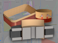
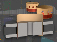
I used three pieces of felt (shown later). The main one is a large rectangle with a cutout that is nearly square with thin 1/2” wide strips above and below the tweeter. The thickness is also 1/2”. The two thinner strips 3/8” thick and 3/4” wide provide a stepped transition that is better than a full thickness piece.
The last piece is 1/2” wide, 3/4" thick (1/2” will do), and the width of the baffle.
This piece provides the primary reduction for the diffraction caused by the midrange unit itself. A driver diaphragm produces quite a bit of diffraction.
You’ll see the improvement made with each additional piece.
The curves in Fig. 1 show how dramatic the difference can be. They measure the baffle in Photo 1 with (yellow curve) and without (blue curve) felt applied. The tweeter (a 3/4” Hiquphon OW1) is especially good for demonstrating diffraction due to its extremely wide dispersion. The midrange is a Scan-Speak 13m/8640. All measurements in this article were taken on the tweeter axis at 1m using LAUD (now discontinued) and displayed using Praxis (currently available), both from Liberty Instruments.
Figure 2 shows the magnitude of the changes. This is the result of normalizing the response with felt to the response without felt. Note the expanded vertical scale of 3dB/line. It shows that there is a change of ±3dB or more.
Placement Breakdown and Results
Each piece of felt and its placement has different results. This will be true for every baffle, but there is commonality from one baffle to the next. I took a series of measurements one for every change in the felt as it was applied and then superimposed them to show the changes.
I have settled on 1/2” thickness for most of the felt that I use. I tested shallower pieces, which work, but not as well. Thickness over 1/2” is in the area of diminishing returns. In fact, there is a point at which it can be too thick. This is because felt is not 100% absorptive. It reflects a small percentage of the sound wave.
If it’s too thick, it starts to introduce its own reflective problems. If you were to use a lower density, then maybe thicker felt would help. I have not tried that approach, but the felt can start to sag if it’s not dense enough.
The piece of felt shown in Photo 2 is the simplest one and is always useful. It does not necessarily need to be the full width of the baffle to be effective.
The aesthetics also are not bad. All systems, including flat baffles, would benefit from this.
The larger the adjoining driver the more diffraction occurs. This is the one piece that may offer more of a benefit if it was thicker (maybe 3/4”). It also can be up to 1” in width before you reach the point of diminishing returns.
It’s likely that more than driver diffraction control occurs with this piece.
Some of it is probably from the baffle offset. I added more felt later on the side of it that directly faces the tweeter. Notice in Fig. 3 just how much influence there is in the range of 1.5kHz to 3.5kHz. This is where the crossover is likely to be placed, making it difficult to get a smooth transition. There is still too much diffraction at this point.
I determined the shape by making a series of tests with different sizes and shapes until I found what I believed to be the optimum. Photo 3 shows the primary diffraction control block for the tweeter. It’s cut from a single piece of felt.
Figure 4 shows the difference without felt (blue) and with the current felt application (yellow). The yellow curve clearly shows that the response is starting to look more linear, especially above 4kHz.
This is a reasonable stopping point for those who may not need to get every possible bit of diffraction control. The crossover network would likely still need to be more complex, or at least would take more time to produce.
If you use only this piece, then it would be better to have a smaller opening, at least in width. A very slight overlap onto the tweeter faceplate is acceptable and may improve it. Don’t place it closer than about 1 1/2” from the center of the tweeter.

I found that a stepped felt profile provided a better response than the full 1/2” depth overall. I’m not sure why this is so, but the measurements clearly showed this to be more favorable.
Figure 5 shows the final response (including the felt around the midrange) and the response with the 1/2” strips removed.
I was amazed at this difference.
I didn’t think that the dispersion of this driver was wide enough to need diffraction control, but testing showed that it, too, has a better response with some felt around it. Incidentally, the felt placed around the midrange made a minor improvement in the tweeter response.
Midrange Driver Improvements
Prior to writing this article, I had paid little attention to the midrange unit, thinking that it would not benefit significantly from a felt application. However, I had noticed an unusual improvement with the piece placed below the midrange when I slid it back as it sat on the woofer box (to improve the phase response relative to the woofer). I placed felt there to absorb reflections from the top of the woofer box. I was surprised to see a better response than placing the MT module flush with the front of the woofer box. There is a natural bump associated with this driver in the middle of its passband that leveled to a degree by the surface reflection.
This prompted me to test more felt on the midrange driver. It proved to be very useful, at least for this driver.
It is a smallish midrange unit and has much wider dispersion than many midrange units.


Figure 7 is the midrange response without felt normalized by the response with felt. It shows in absolute terms how much change occurs by adding the felt to the midrange unit. There is close to ±2dB of change.
Example 2
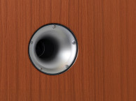
Photos 5 and 6 show another example of a baffle that you might consider to have too much diffraction. That is true if left untreated. However, fully treating it with felt although objectionable from an aesthetic standpoint shows just how effective felt can be.
Photo 5 shows the baffle in untreated form. I have quite a few felt pieces to use for testing. This is how I determine a somewhat optimal opening shape and what to avoid.
Photo 6 shows the full treatment of felt that was the most effective. It’s not pretty, but it works well. I will be replacing the ring and felt, however, with a rectangular piece as shown on the first box.
Interestingly, the single piece of thinner felt was sufficient for the tweeter. A second piece made little difference. But it had to be on the side where the baffle edge was closer. In contrast, the first example showed significant improvement with each of the two pieces applied.
Figure 8 shows the measurements of this baffle before and after treatment. It’s easy to see the improvement that it makes.


What Does It Really Do?
I believe that this is more than just an exercise in flattening a particular response on some axis. True, it does do that. But I see two benefits to using edge treatment, whether you use felt or roundovers.
First, it makes designing the crossover much easier. If diffraction effects are not removed, then the dips and peaks seen on any particular axis will change more drastically if you move off-axis. Reviews in magazines that provide measurements will publish something to the effect that some dip on-axis is “filled in” by a consequent increase at that same point off-axis.
A crossover design requires more than just optimizing the response on a single axis. The power response, which is the sum of all response axes that contribute to the entire reverberant sound field (i.e., the listening room) is a significant component. Reducing some on-axis dip or peak may actually be counterproductive because that same dip or peak will change when the axis changes if the baffle is left untreated. The felt treatment helps to linearize the on-axis response and reduces the changes heard as you move off-axis.
There’s much less “guessing” of what the off-axis response may be because both the on-axis and off-axis responses are improved by edge treatments.
Second, I believe that any signal (such as diffraction effects) that interferes with the direct signal and is not part of the reverberant environment should be avoided if at all possible. Diffraction is a time-delayed direct signal, inverted in phase, lower in magnitude, and far from linear since it is directly related to the drivers’ directionalities and is related to the distance from the driver to each diffracting point. It alters the direct signal in a comb effect. I think that this affects the low-level detail and imaging of the system.
Conclusion
The examples presented here dramatically show the effects of diffraction and how it can be significantly controlled. It’s very cost effective and can be aesthetically acceptable, while, at the same time, is simple to apply. I never make a baffle without edge and between-driver treatment. Try it, I think you’re likely to agree.
An article originally published in audioXpress, June 2005


