Using an oval (elliptical) voice coil shape to defeat cone and dome standing wave modes is obviously a compelling concept. By driving the diaphragm asymmetrically, what you get is an “infinite” number of Eigen frequencies, but with less contribution for each frequency and overall lower distortion. Driving the diaphragm symmetrically you get a finite number of Eigen frequencies with a higher contribution combining at certain frequencies producing the coloration modes. If you have had a chance to go through Chapter 14 of the new 8th Edition of the Loudspeaker Design Cookbook, you will see that I am a big fan of Ellipticor (I’m also a big fan of a number of different technologies in the industry!) and do think it results in a highly detailed and uncolored sound quality due to the oval voice coil technology.
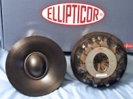
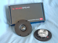
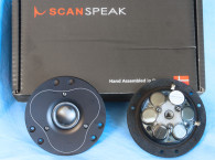
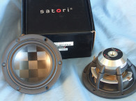
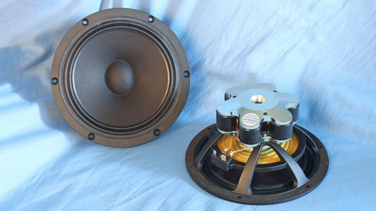
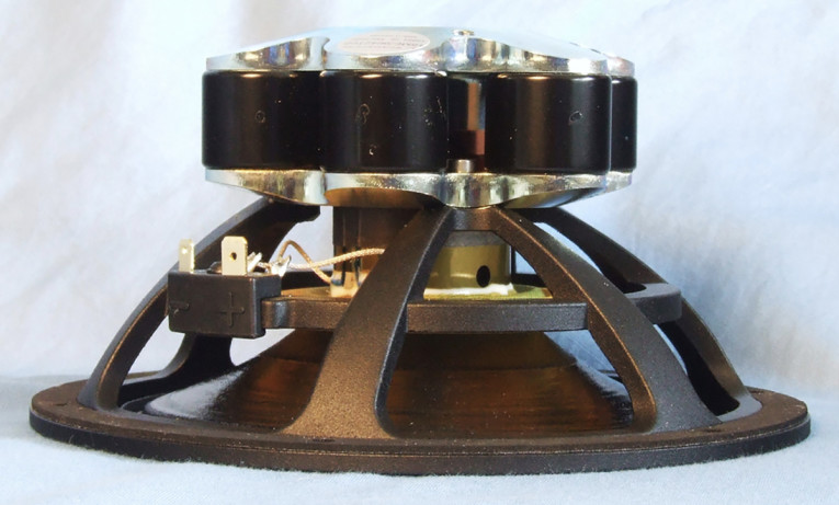
Overall, the 7” 18ME midrange (Photos 1-3) is based on the same frame (less the magnetically attached aluminum trim ring) and same AirCirc motor structure as the Scan-Speak 18WE woofer. The 18ME uses six 28mm diameter × 21mm tall neodymium (neo) magnet slugs in a circular array with copper shorting rings, and a vented titanium voice coil former wound with round copper wire, all part of the patented Symmetrical Drive SD-2 motor format. The motor system has a 5mm gap height and a 10.4mm voice coil height giving it 2.7mm Xmax (compared to the 7.2mm Xmax of the 18WE), which is both appropriate and typical of midrange transducers.
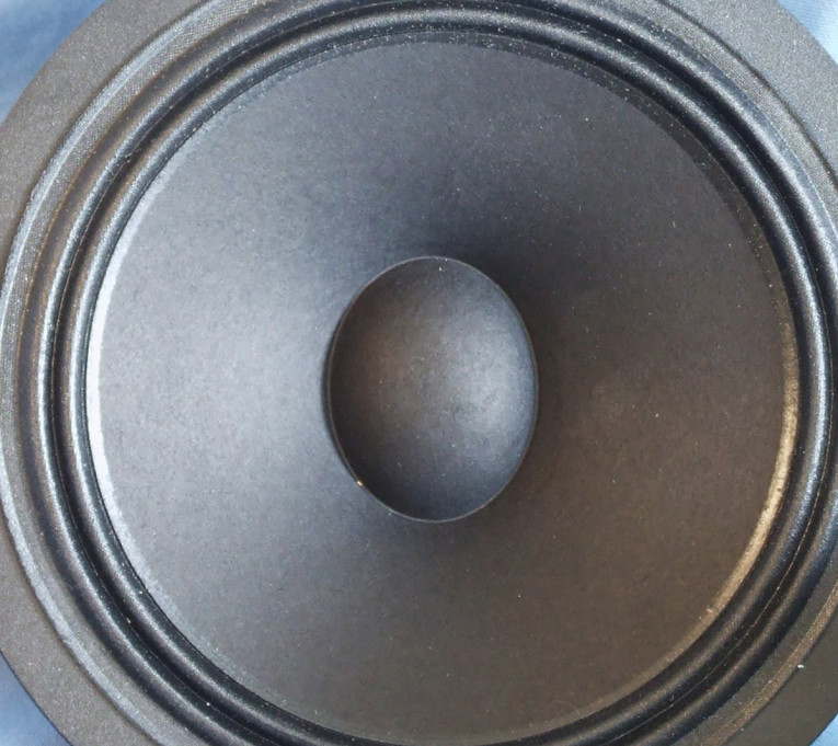
Other features include an uncoated paper cone and uncoated paper elliptical dust cap. While the 18ME has a similar 4” diameter flat cloth spider as the 18WE, the midrange’s surround departs from the typical NBR Scan-Speak woofer surround and as with the new 38WE 15” woofer, has a coated pleated M-type cloth surround similar to those used in pro audio. Last, the voice coil tinsel leads are terminated to a pair of gold-plated solderable terminals.
I began characterizing the new Scan-Speak 18ME/9642 6.5" midrange using the LinearX LMS analyzer and the Physical LAB IMP Box (which is the same type test fixture as a LinearX VI Box, used for measuring voltage and current separately). Sweeps were generated with the driver securely mounted in free air at 0.3V, 1V, 3V, 6V, 10V, and 15V. The measured Mmd that was provided by Scan-Speak was used rather than a single 1V added (delta) mass measurement. It should also be noted that this multi-voltage parameter test procedure includes heating the voice coil between sweeps for progressively longer periods to simulate operating temperatures at that voltage level (raising the temperature to the first- and second-time constants). The 15V curves were sufficiently linear to get a good curve fit, and at first glance is a bit surprising for a 2.7mm Xmax midrange, however, with the high Fs, the driver remains stable at the higher voltage.
The 14 stepped sine wave sweeps for each woofer were further processed with the voltage curves divided by the current curves to produce impedance curves. Phase curves were generated using the LEAP phase calculation routine, after which the impedance magnitude and phase curves plus the associated voltage curves were then copy/pasted into the LEAP 5 Enclosure Shop software’s Guide Curve library. This data was then used to calculate parameters using the LEAP 5 LTD transducer model. Because most all manufacturing data is being produced using either a standard transducer model or in many cases the LEAP 4 TSL model, I also generated LEAP 4 TSL model parameters using the 1V free air that can also be compared with the manufacturer’s data. Figure 1 shows the 18ME 1V free-air impedance plot.

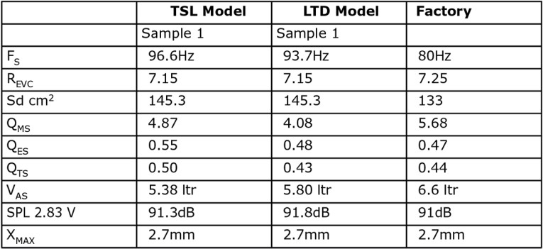
Unfortunately, the second sample had a floating point data error I was unable to correct, and since I can no longer consult the program’s author (RIP Chris Strahm), I will only provide T-S parameter data on one sample (my apologies to Scan-Speak). Table 1 compares the LEAP 5 LTD and LEAP 4 TSL T-S parameter sets for the single Scan-Speak 18ME/9642T00 midrange driver sample along with the Scan-Speak factory data.
After examining the frequency response of the 18ME, it looks like the 18ME will work well high-passed somewhere between about 300Hz to 600Hz, depending on the baffle reinforcement at the low end. Obviously, this driver will not be operating in its piston range, so enclosure simulations or Klippel LSI3 data are not particularly relevant. However, if you are developing a passive high-pass network for the 18ME, knowing approximately where the midrange cavity resonance is located will be is important.
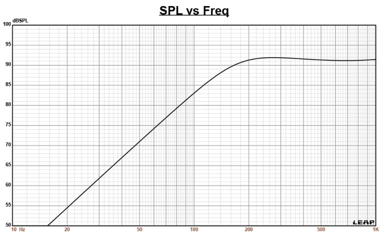
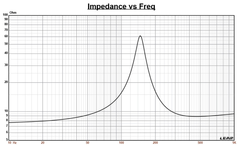
As such, I performed an enclosure simulation with 180in3 volume with 50% fill material (fiberglass) to achieve a Qtc=0.7 Butterworth sealed box target response, but only at 2.83V as we are not concerned with excursion in the piston range. Figure 2 shows the sealed box SPL showing the F3 at 148Hz (Qtc=0.7), while Figure 3 gives the impedance at 2.83V. This information is useful, especially if you are developing a high-pass filter and octave or less above the 148Hz resonance that may require the use of an LCR band reject filter to reduce the impedance into which the high-pass filter will be working. Obviously, if you are using active filters, this is not an issue.
Next, I mounted the Ellipticor 18ME midrange in a foam-filled enclosure that had a 12”×8” baffle and then measured the device under test (DUT) using the Loudsoft FINE R+D analyzer and the GRAS 46BE microphone (courtesy of Loudsoft and GRAS Sound & Vibration). The driver was measured both on- and off-axis from 200Hz to 20kHz at 2V/0.5m, normalized to 2.83V/1m using the cosine windowed fast Fourier transform (FFT) method. Figure 4 gives the Scan-Speak 18ME/9642T00 on-axis response, indicating a smooth rising response from 300Hz to 7kHz with 5dB peak centered on 4kHz.
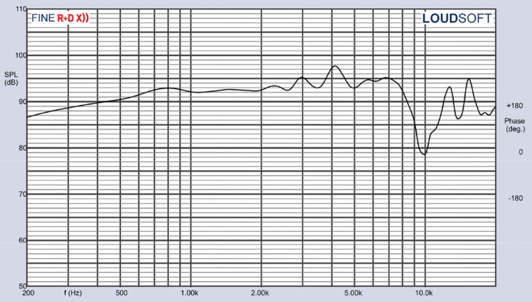
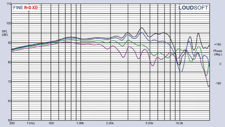
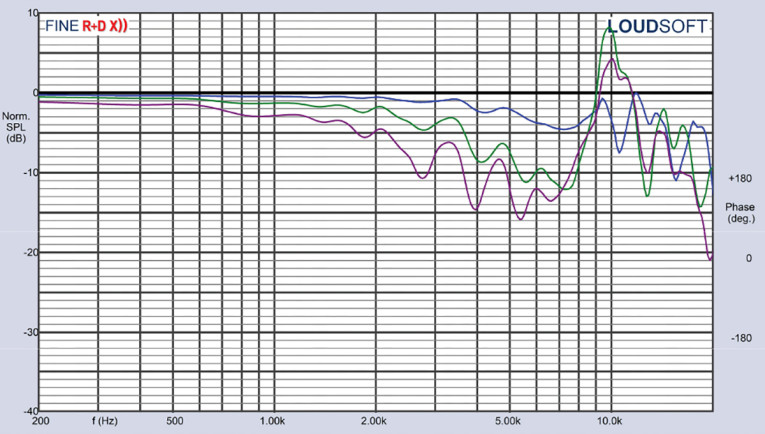
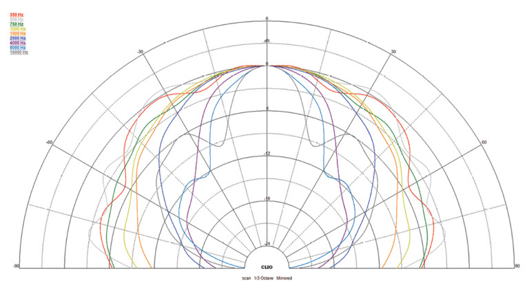
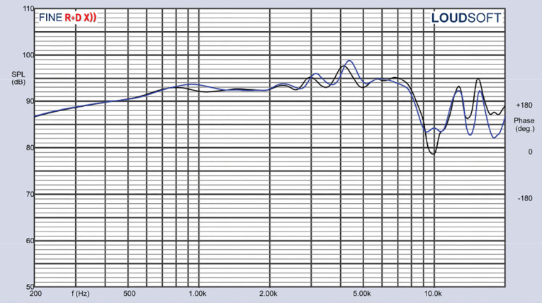
Figure 5 displays the on- and off-axis frequency response at 0°, 15°, 30°, and 45°, showing the typical directivity for a 6.5” to 7” woofer. The -3dB at 30° with respect to the on-axis curve occurs at about 2.4kHz, so is a reasonable frequency for a low-pass crossover. Figure 6 shows the normalized version of Figure 5. Figure 7 shows the CLIO polar plot (in 10° increments and 1/3 octave smoothing). And finally, Figure 8 displays the two-sample SPL comparisons for the Scan-Speak 18ME/9642T00 midrange driver, showing a match ≤ 1dB throughout the operating range.
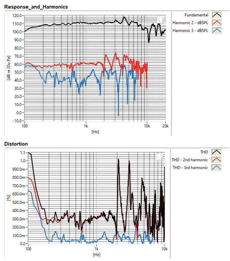
For the last remaining series of tests, I again employed the Listen, Inc. SoundCheck AudioConnect analyzer and SCM ¼” microphone to measure distortion and generate time-frequency plots. For the distortion measurement, I mounted the 7” 18ME/9642T00 midrange driver rigidly in free air and set the SPL to 94dB at 1m (3.54V) using a pink noise stimulus. I then measured the distortion with the Listen microphone placed 10cm from the driver. This produced the distortion curves shown in Figure 9, with third harmonic distortion staying between >0.2% to 0.3% from 300Hz to 7.5kHz.
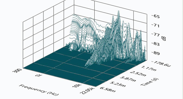
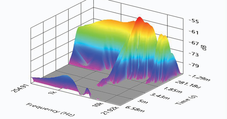
I then used SoundCheck to get a 2.83V/1m impulse response for this driver and imported the data into Listen’s SoundMap Time/Frequency software. Figure 10 shows the resulting cumulative spectral decay (CSD) waterfall plot. Figure 11 displays the Short-Term Fourier Tansform (STFT) surface plot.
This is a rather landmark driver for Scan-Speak, as it is the company’s first OEM-only transducer, and I’m sure there will be more dedicated OEM drivers in the future. For the 18ME specifically, this is another well-performing low-coloration Ellipticor driver that will find use in three- and four-way system applications. For more information, visit www.scan-speak.dk. VC
This article was originally published in Voice Coil, August 2023.