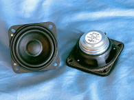
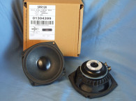
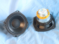
It is interesting to note that Mobile Fidelity Sound Labs (MOFI) recently hired loudspeaker engineer extraordinaire Andrew Jones to produce a new loudspeaker. What Jones came up with rather departs from the usual home audio paradigm, as seen in Photo 1. Jones developed what looks like a 10” pro sound woofer with a coincident 1.25” cloth dome tweeter. The MOFI SourcePoint 10 is a 91dB 2.83V/1m two-way crossed at 1.6kHz, which is very similar to what can be done with the driver featured in this month’s Test Bench—Faital Pro’s 10HX230 10” pro sound coax (Photos 2–4).
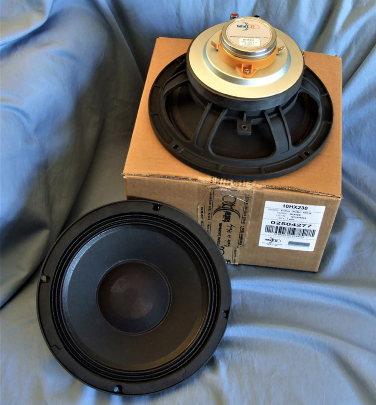

That said, the new Faital Pro 10” 10HX230 coax driver is the latest edition to the company’s extensive 12 model line of compression driver/woofer coax transducers. In terms of features, the 10HX230 woofer is built on a proprietary six-spoke cast-aluminum frame. Cooling for the woofer voice coil is provided by 12 7mm×2mm frame vents located below the spider (damper) mounting shelf, and by the aluminum conic horn attached to the woofer pole vented pole piece (Photo 4). As with any driver with a phase plug, there is also a convection path out the front of the voice coil, plus the cooling from the fairly large ceramic motor mass cooling.

The 10HX230 woofer has a curvilinear uncoated paper cone suspended by a three-roll coated cloth surround and a variable height roll 5” flat cloth spider. The cone assembly is connected to a 65mm (2.56”) diameter voice coil wound with aluminum wire on a glass fiber former. Driving the voice coil/cone assembly is a 155mm×18mm ferrite magnet sandwiched between a polished and milled front plate and a cast T-yoke that also includes a distortion reducing aluminum shorting ring (Faraday Shield). Tinsel leads connect to a pair of color-coded chrome-plated push terminals. Power handling is rated at 500W with 96dB 1W/1m sensitivity.
With the horn output mounted coincident with the woofer, the compression driver has its own separate neodymium ring magnet motor assembly attached to the back plate. This compression driver is comprised of a Keytone Polymer diaphragm driven by a 37mm (1.46”) diameter underhung (Xmax=2.5mm) voice coil constructed with a Kapton former wound like the woofer voice coil with aluminum wire.
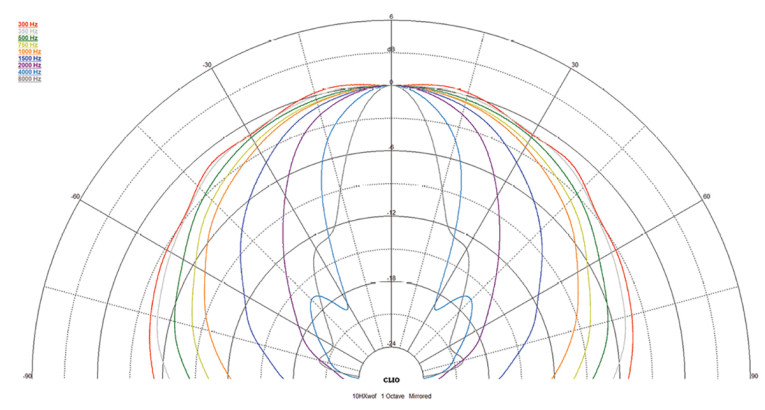
The annular-shaped Keytone Polymer diaphragm fires into a short aluminum conical-shaped horn, which brings the 1W/1m sensitivity to 107dB with a recommended crossover frequency of 1.7kHz. Figure 1 shows the directivity plot of the compression driver/conical horn. Terminals for the compression driver are located on the injection-molded compression driver assembly bolted to the woofer’s T-yoke. Applications for the 10HX230 coax are primarily as a stage or studio monitor, or as a PA fill driver for small or separated spaces such as under balconies.

Testing began with the woofer half of this coax driver using the LinearX LMS and Physical Box IMP Box (the same type voltage/current fixture as the legacy LinearX VI Box) to create both voltage and admittance (current) curves with the driver clamped to a rigid test fixture in free-air at 0.3V, 1V, 3V, 6V, 10V, 15V, 20V, and 30V with oscillator left on between sweeps to simulate the actual thermal process over time. The woofer voltage curves were linear enough to get a sufficient curve fit out to 30V such that none were discarded.
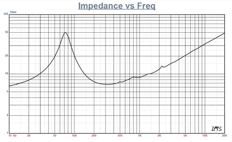
Following my established protocol for Test Bench testing, I no longer use a single added mass measurement and instead use the company-supplied Mmd data (25.7 grams for the 10HX230). The collected data, in this case the 16 550-point (0.3V to 30V) sine wave sweeps for each Faital Pro sample were post-processed and the voltage curves divided by the current curves to generate impedance curves, with the phase derived using the LinearX phase calculation methodology, and along with the accompanying voltage curves, imported to the LEAP 5 Enclosure Shop software. Figure 2 shows the woofer’s 1V free-air impedance curve, along with the compression driver impedance curve. Table 1 compares the LEAP 5 LTD/TSL Thiele-Small (T-S) parameter data and factory parameters for both of the Faital Pro 10HX230 samples.

Parameter measurement results for the Faital Pro 10HX230 were very close to the published factory data, except the Xmax numbers. Xmax differs only because Faital, like several other manufacturers, includes fringe-field compensation in their Xmax number. The formula they use is Xmax = [(winding depth - magnetic gap depth)/2] + (magnetic gap depth/3) as opposed to the strict convention of Xmax = (winding depth - magnetic gap depth)/2. This is similar to the Xmax + 15% figure I use to establish maximum output for the box simulations.
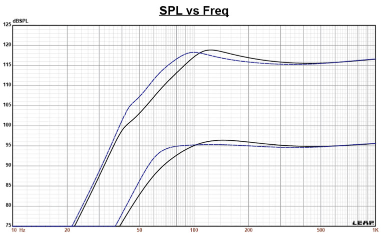
As I do for all Test Bench woofer analysis, I proceeded to set up two computer enclosure simulations using the LEAP LTD parameters for Sample 1. This resulted in a QB3 vented box alignment box with a 0.7ft3 volume and 15% fiberglass fill material tuned to 71Hz. A second simulation was produced using an Extended Bass Shelf (EBS) alignment (a larger enclosure with a lower tuning) in a 1.25ft3 volume, also with 15% fiberglass fill material and tuned to 65Hz.
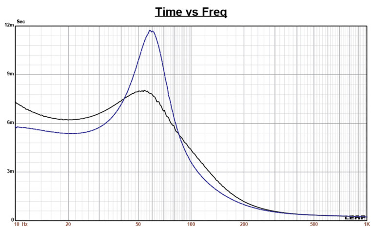
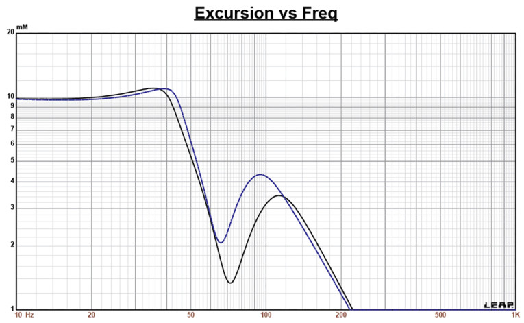
Figure 3 displays the results for the Faital Pro 10” woofer in the two vented enclosures at 2.83V and at a voltage level sufficiently high enough to increase cone excursion to Xmax + 15% (5.4mm for the 10HX230). This produced a F3 frequency of 84Hz (-6dB=68 Hz) for the QB3 enclosure, and a –3dB=60Hz (-6dB=54Hz) for the EBS vented box. Maximum linear excursion (Xmax + 15%) resulted in 119dB at 40V for the QB3 box simulation and 119dB at the same 40V input for the EBS vented enclosure. Figure 4 shows the 2.83V group delay curves. Figure 5 shows the 40V excursion curves. The 40V number was chosen because both alignments exceeded the Xmax + 15% number around 50Hz. With an appropriate high-order high-pass filter, both enclosures would produce higher output, only limited by their thermal power handling capability.
Klippel analysis for the Faital Pro woofer half of the 10HX230 was performed this month at Warkwyn by Jason Cochrane using the Klippel KA3 modular analyzer. Please note that longtime contributor to Voice Coil Patrick Turnmire will no longer be providing Klippel analysis on the DA2 analyzer, instead it will be performed at my office on the DA2 in the near future. That said, Patrick Turnmire is one of the absolute best transducer engineers it has been my pleasure to work with over the years, a seriously professional musician/songwriter/drummer, and a good friend. I would like to take this opportunity to publicly thank him for the outstanding contribution he has made to Voice Coil magazine over the years.
The Bl(X) curve for 10HX230 shown in Figure 6 is moderately symmetrical and reasonably broad for a 10” non-subwoofer driver, along with being slightly “tilted” and small amount of offset. The Bl symmetry curve shown in Figure 7 shows less than 0.6mm rearward offset once the graph reached a place of reasonable certainty at the 3mm excursion point, falling to nearly zero offset by the 4.7mm Xmax.
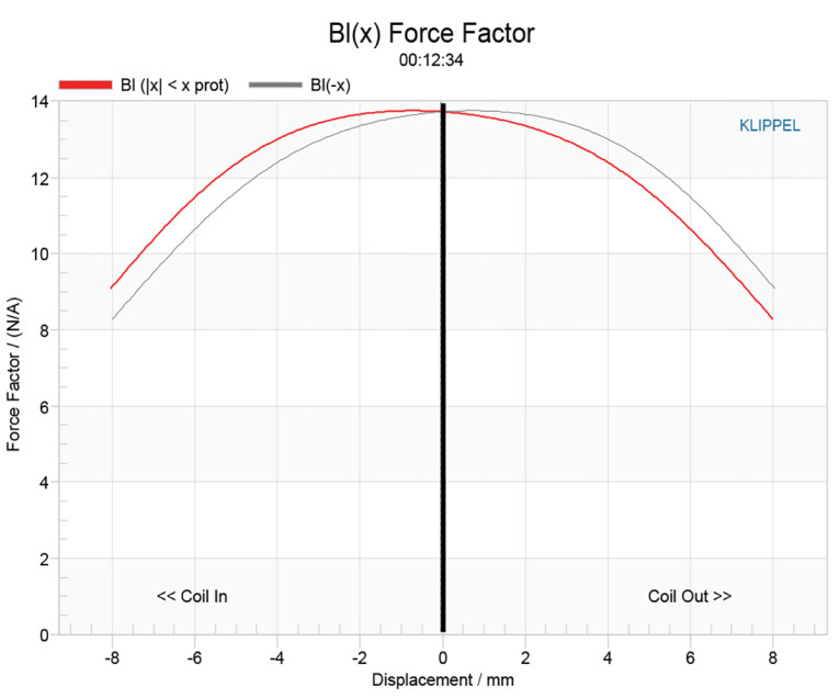
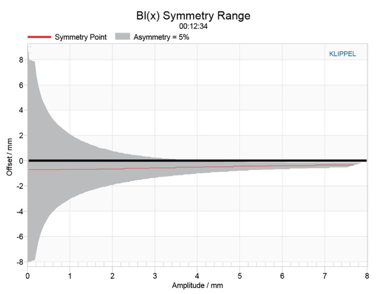
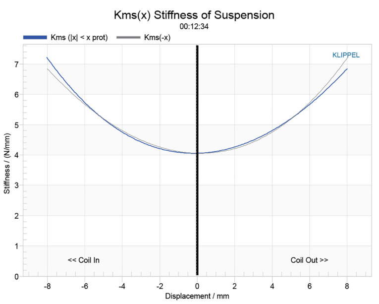
Figure 8 and Figure 9 show the Kms(X) and Kms symmetry curves for the 10HX230 coax. The Kms stiffness of compliance curve (Figure 8) is also broad and symmetrical and with practically no offset or tilt. The Kms symmetry range curve (Figure 9) indicates a trivial 0.013mm forward offset at the 4.7mm Xmax point, and does not vary much through the entire operating range of this transducer’s excursion profile.

Displacement limiting numbers calculated by the Klippel analyzer using the full-range woofer criteria for Bl was XBl @ 82% (Bl dropping to 82% of its maximum value) was 5.42mm (slightly greater than the Xmax for the 10HX230) for the prescribed 10% distortion level. For the compliance, XC @ 75% Cms minimum was 4.45mm, which means that for the Faital woofer section of this coax driver, the compliance is the more limiting factor for getting to the 10% distortion level, but for all practical purposes, they really are equal contributors. What is more significant is that both numbers exceed the 4.7mm physical Xmax of this driver. This is a very well-designed motor system.
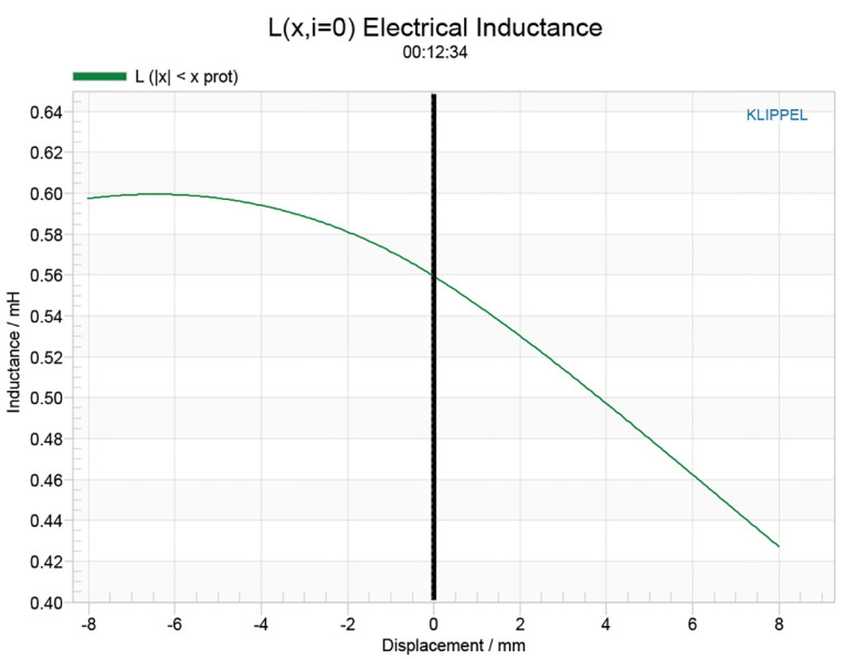
Figure 10 gives the inductance curves Le(X) for the 10HX230. Inductance will typically increase in the rear direction from the zero rest position as the voice coil covers more pole area, which is what is happening here, typical of this type of ferrite motor that incorporates an aluminum demodulation (shorting) ring. The maximum inductance swing for this driver from Xmax in to Xmax out is a very low 0.12mH, which is excellent performance for this large a ferrite motor.
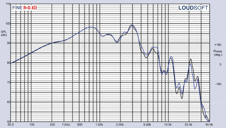
With the Klippel analysis completed, I proceeded to mount the Faital Pro 10HX230 in an enclosure that had a 16”×11” baffle, filled with foam-damping material. I then measured both the woofer and the compression driver on- and off-axis from 200Hz to 40kHz at 2V/0.5m, normalized to 2.83V/1m using the Loudsoft FINE R+D analyzer and the GRAS 46BE microphone (courtesy of Loudsoft and GRAS Sound & Vibration). Figure 11 gives the 10HX230 woofer’s on-axis response along with the compression driver’s on-axis response. The woofer has a smooth rising response out to 800Hz followed by a depression in the response centered on about 1.8 kHz and begins the typical second-order low-pass roll-off at 2.9kHz. For the compression driver, the response extends from 1.3kHz out to 20kHz. The response SPL drops about 13dB between 5kHz to 10kHz and would require some equalization, analog or DSP.
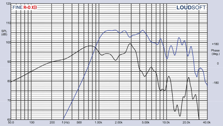
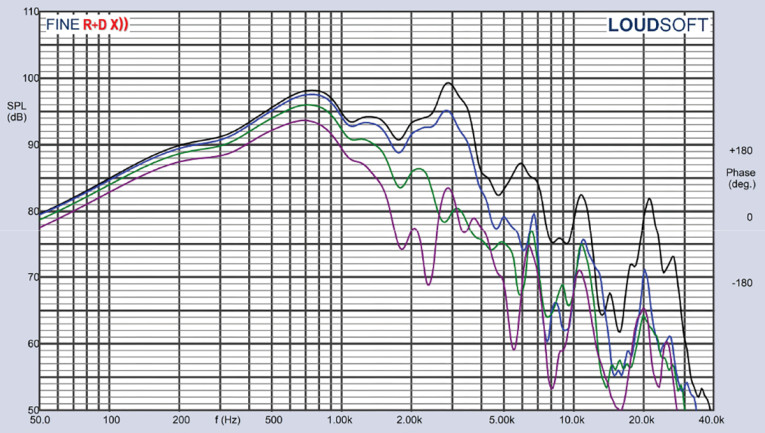
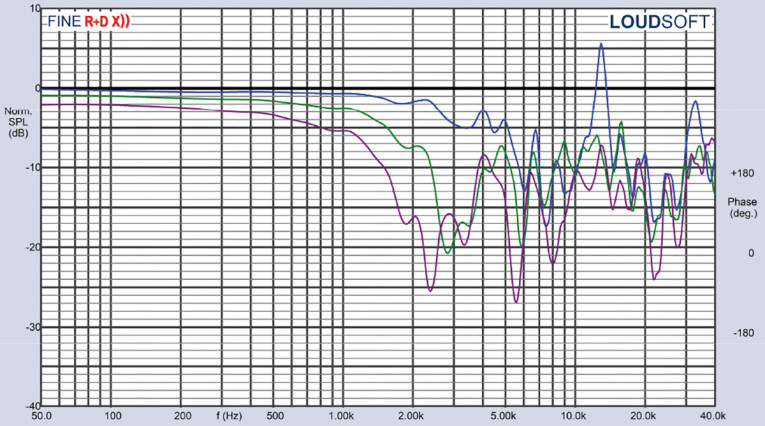
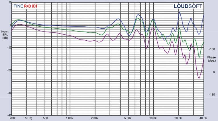
Figure 12 depicts the woofer’s on- and off-axis frequency response at 0°, 15°, 30°, and 45°. The -3dB at 30° with respect to the on-axis curve occurs at 2kHz, which coincides with recommended crossover frequency for the compression driver and conical horn. Figure 13 gives the normalized version of Figure 12, and Figure 14 depicts the CLIO 180° polar pot (in 10° increments). And last, Figure 15 gives the two-sample SPL comparisons for the 10HX230 woofers, both samples matched within 0.5dB to 1dB, which is within the woofers operating range when crossed over at 1.7kHz.
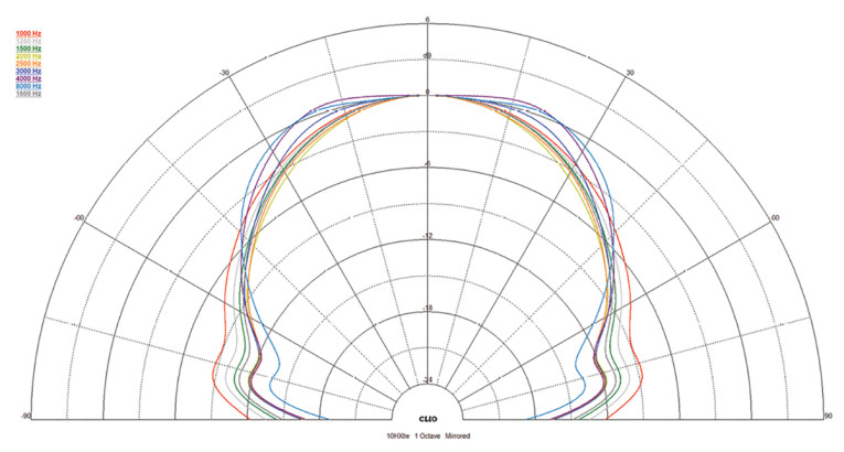
For the compression driver, starting with the impedance curve shown in Figure 16, the minimum impedance is 6.44Ω at 3.48kHz with a 5.4Ω DCR. For frequency response, Figure 17 gives the on- and off-axis horizontal frequency response out to 45°, with the normalized version shown in Figure 18, and the CLIO 180° polar plot (processed in 10° increments) shown in Figure 19. Figure 20 depicts the two-sample SPL comparison for the compression driver half of the 10HX230 coax, which is within 0.5dB to 2dB from 1.5kHz to 20kHz.


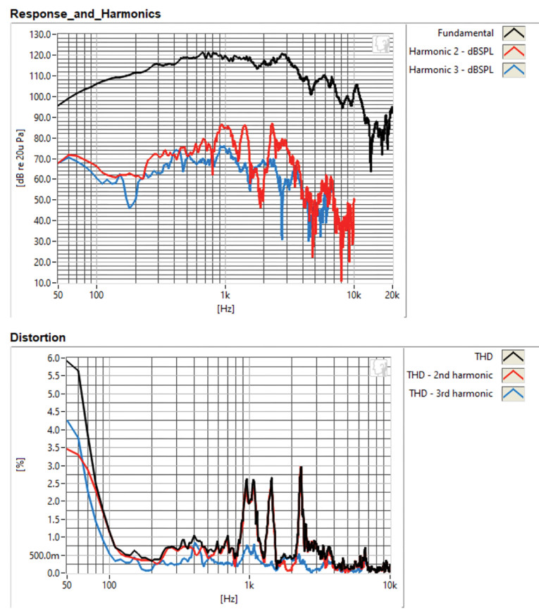
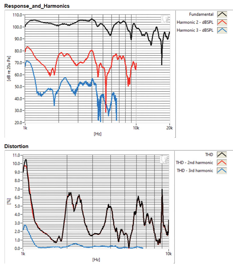
The final group of tests was performed using the Listen, Inc. AmpConnect analyzer and SC-1 microphone (courtesy of Listen, Inc.) along with the SoundCheck software to measure distortion and generate time-frequency plots. Setting up for the distortion measurement consisted of mounting the driver rigidly in free-air, and setting the voltage level to raise the SPL to 104dB for the both woofer and the compression driver at 1m using a pink noise stimulus. I then measured the distortion with the Listen microphone placed 10cm from the woofer dust cap and the tweeter horn. This produced the distortion curves shown in Figure 21 for the woofer (10.3V) and Figure 22 for the compression driver (2.75V).
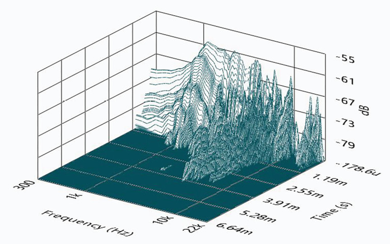
With the distortion test completed, I set up SoundCheck to produce a 2.83V/1m impulse response for both the woofer and the compression driver and imported the data into Listen’s SoundMap Time/Frequency software. The resulting cumulative spectral decay (CSD) waterfall plots are shown in Figure 23 for the Faital Pro 10HX230 woofer and in Figure 24 for the compression driver.
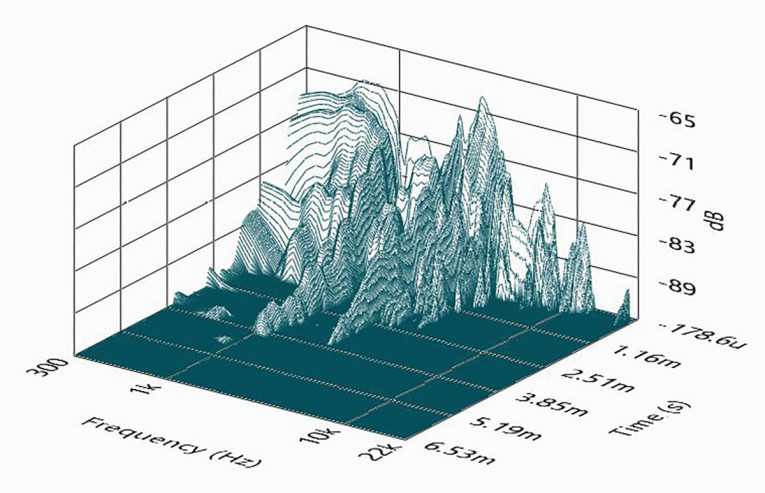

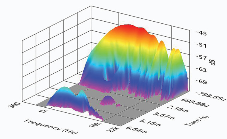
For the final SoundMap graphic output, Figure 25 gives the woofer’s Wigner-Ville logarithmic surface map (chosen for its better low-frequency performance). Figure 26 displays compression driver’s Short Time Fourier Transform (STFT).
All the impedance, SPL, distortion, and time domain data taken to characterize the Faital Pro 10HX230 describes a well-designed pro sound coax driver, which is what you expect from an OEM such as Faital Pro. Faital Pro’s products are consistently well-engineered with good performance characteristics and trade-offs, with the 10HX230 representing another good example of the company’s engineering and manufacturing skills. For more information, visit the Faital Pro website at www.faitalpro.com. VC
This article was originally published in Voice Coil, March 2023.