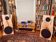
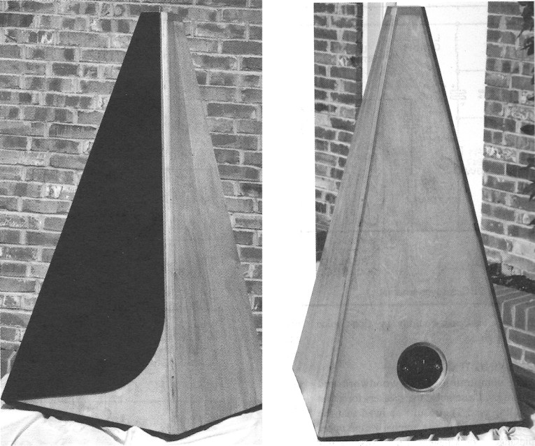
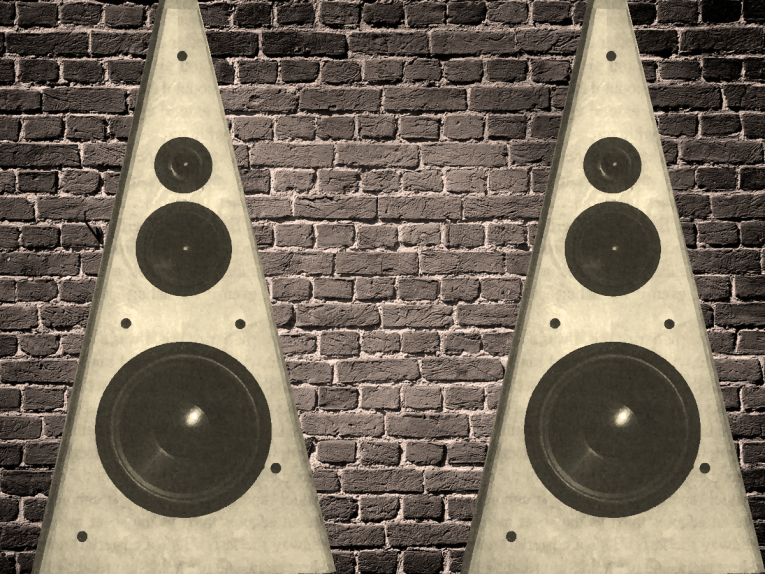
Pyramids have some distinct advantages over box-type speaker cabinets. For example, the nonparallel walls minimize standing-wave effects and the slanted front improves the time adjustment of the drivers (Photo 1). Furthermore, the front is wide enough at the base to accommodate the woofer, and narrow at the top, where the tweeter is located. This minimizes diffraction effects and helps to improve sound dispersion. The panel width also varies from bottom to top, which distributes panel resonances. The only disadvantages of which I am aware are that a pyramid is more complicated to build and, for a given height and volume, it requires more floor space than, for example, a tower speaker.
The Drivers
The tweeter I used for this design is a Vifa D27TG-45-06. This 1" driver, manufactured in Denmark, features a coated diaphragm of fabric, ferrofluid damping, and a replaceable voice coil. It costs $23, and is probably one of the best choices for less than $50 per pair.
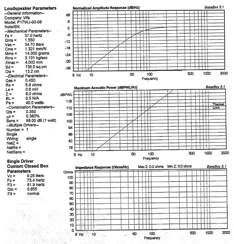
The midrange is a Vifa Pl 7WJ-00-08, actually a 6½" mid/woofer. It comes with a magnesium basket, mineral-filled polycone, and rubber surround, and costs about $35.
With the pyramid's restricted volume, I needed to search for a decent woofer suitable for a closed design of approximately 50 ltr, and close to my budget figure of $60. With a 6½" driver used as a midrange, I could choose a very low crossover point-in other words, a fairly large woofer.
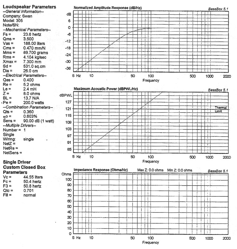
I finally decided the Swan 305 was a good choice. This driver is 12" in diameter, has a polypropylene diaphragm with foam surround, and requires a volume of about 50 ltr for a Qtc of 0.7 in a sealed cabinet. Last, but not least, it costs $58, fitting my budget perfectly.
The Crossover
The crossover is a three-way design with 12dB/octave slope. Vifa recommends crossing over the tweeter at 3.5kHz, a relatively high crossover point for the 6½'' midwoofer. However, the frequency-response and dispersion curves for the Pl 7WJ-00-08 show that the driver rolls off at 5kHz on-axis and is only 2-3dB down at 3.5kHz, measured under 30°. Also, I was not yet willing to trade the power-handling capabilities of the tweeter for a better dispersion at a lower crossover frequency.
The beauty of the large midrange is that it can easily be crossed over below 500Hz. This moves the crossover points out of the most sensitive audible spectrum. I finally chose a crossover point of 350Hz between woofer and midrange.
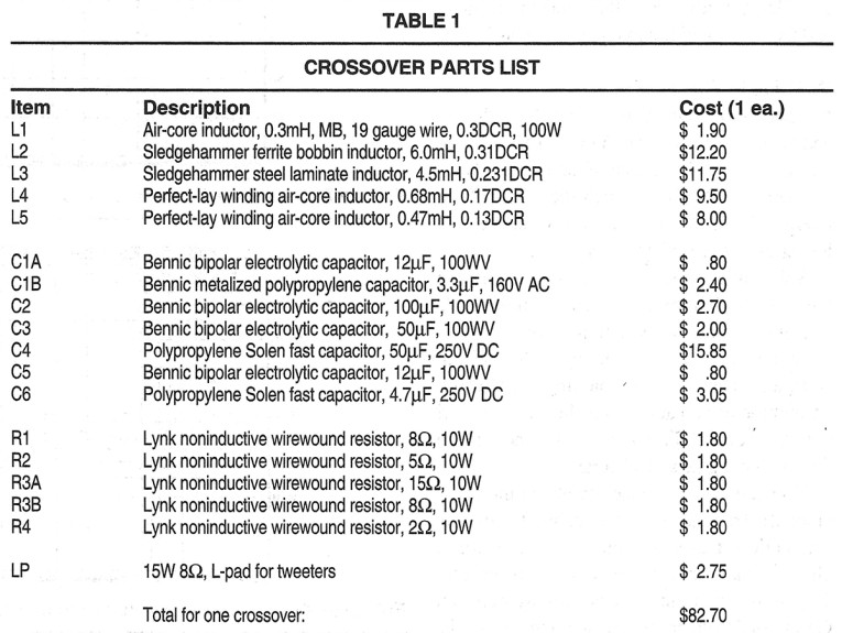
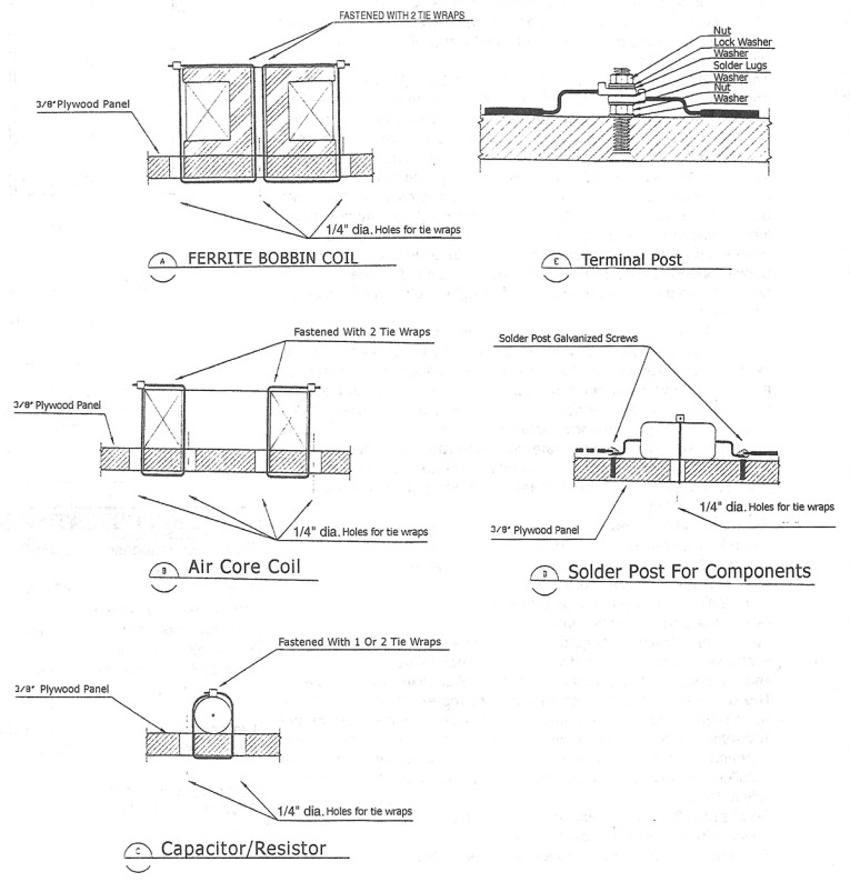
I started the design by measuring the impedance curves of the woofer and midrange drivers and compensating the impedance rise. I calculated the required values for coils, capacitors, and resistors manually. The crossover is constructed with parts of excellent quality in the signal path, and parts of acceptable quality elsewhere (Table 1).
Listening Test
After completion of the woodwork and crossovers, I assembled the speakers for a first listening test. The results showed that the speakers seemed to overemphasize the upper midrange, approximately at the crossover frequency between midrange and tweeter.
I do not yet possess the tools for measuring frequency response, and I was not willing to spend more time with trial and error to correct the problem. I finally sent my crossover design to Madisound, which offers design services and simulation on LEAP software. I asked them to simulate the response based on my design, and then to improve this design to achieve a flat response. I paid $40 for this service, and after the few required modifications and additions to the existing crossover, the sound improved markedly. Figure 2 shows the crossover schematic.
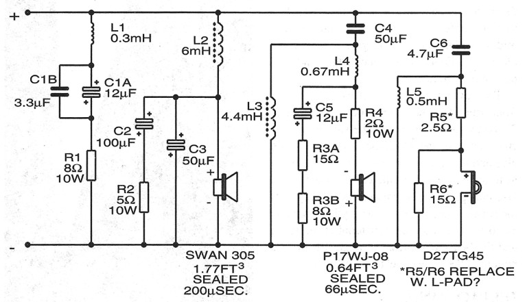
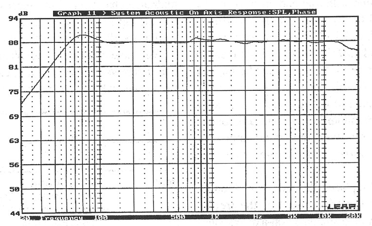
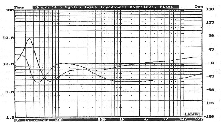
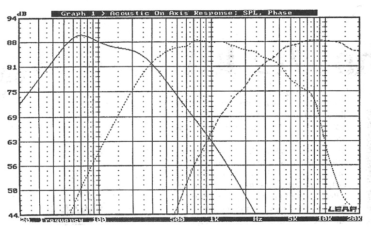
Figure 4 shows the impedance magnitude and phase. Most importantly, the impedance does not drop below 4.5Q, which means the speaker is actually amplifier friendly. Figure 5 shows the simulated response of each speaker. The actual crossover frequencies are at 300Hz and 3.25kHz-from my point of view, close enough.
The Cabinet
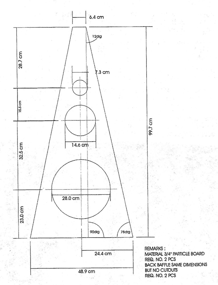
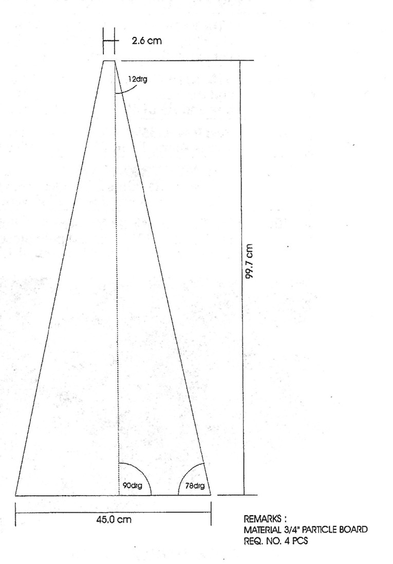
The cabinet is a double-layer construction. The inner cabinet is fabricated from ¾" particleboard, and the outer shell from ¾" birch plywood (Fig. 7). Start by cutting the front, back, sides, and the divider between the woofer and midrange chambers of the inner cabinet. Note that the top and bottom ends of these pieces, as well as the divider, must be cut at an angle.
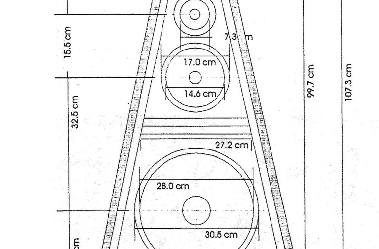
Assemble these parts with plenty of particleboard screws and wood glue, except for the front panel, which you attach only with screws, since you'll need to remove it at a later stage of the project. The dimensions (metric) are shown in Figs. 8 and 9. Cut the holes for the drivers after you get them. Manufacturers do change technical data without notice, and it is difficult to alter the size of one of these holes, especially if you decide to flush-mount the drivers.
I used a belt sander to carry out the final alignment between the cabinet and the top and bottom pieces. Start with 50-grit belts and finish with 100-grit. The whole procedure should not take more than 15 minutes, and it provides an exact fit, even if the cabinet is not exactly rectangular.
The first time I tried this, I was a little bit too enthusiastic with the sander and ran it into the cabinet walls. This is not really a serious problem, since you'll cover the inner cabinet with the birch layer, but if you have had little experience with handling a belt sander, attach a piece of sheet metal as wide as the base of the cabinet with duct tape. This protects the cabinet and leaves an edge as thick as the sheet metal. To sand away the last 1/32" of material, remove the sheet metal and use a fine-grit sanding belt.
Remove the front panel and attach it with screws (no glue) to a 2'x4' birch plywood panel. Mark the centers of the driver cutouts, and drill small pilot holes through both panels. Mark the plywood panel around the perimeter of the particleboard. Separate the two panels and cut out the holes for the drivers on each panel separately with a jigsaw or router.
To flush-mount the speakers, you must use a router. Rout the outer circumference of the driver first, then set the template for the cutout diameter and rout all the way through the material. The centerpiece needs to be attached to the bench with two screws and the front panel with two clamps; otherwise, the center will move and the router will run into the front panel.
Installing Cables
It is easiest to install the cables for the midrange and tweeter at this stage. You can later locate the crossover at the bottom of the woofer chamber. Drill a 3/8" hole through the center of the internal divider. Cut the cables at least a foot longer than you think they need to be.
Solder lugs to the ends that will be located in the woofer chamber, and run the other ends through the hole in the internal divider. Mark the cables as tweeter/midrange, +/- on both ends, and make sure the markings match (use an ohmmeter or battery and flashlight bulb if you are in doubt). Fasten the cables and seal the hole with hot glue and silicone.
You can now permanently attach the particleboard front to the inner cabinet. For this connection, I used silicone as well as wood glue to make sure the cabinet is really airtight. The most important joint is actually between the internal divider and the surrounding walls. If this joint leaks, the woofer will pressurize the midrange chamber, which will have a devastating effect on the performance of the midrange. Once the wood glue is dry, apply plenty of silicone to all inner edges and corners of the cabinet.
The next step is to cut and mount the birch front panel. Cut the panel about ¼" wider and 2" longer than required. Make sure the driver cutouts match, and attach the panel using wood glue and the screws for fastening the drivers so as to apply pressure in the center of the panel. Use clamps to apply pressure at the edges of the panel. I used a router with a piloted straight bit to remove the excess material at the sides, and the belt sander again to align the top and bottom of the birch panel to the cabinet.
The Back Panel
Now you can cut and attach the plywood back panel. First locate and cut the hole for the terminals and tweeter controls. This hole is required, since the lengths of the terminal and potentiometer shaft are not sufficient for a 1 ½" wall thickness. As described for the front panel, I also cut this one larger than required.
It is awkward to use clamps on a pyramid, because the opposite walls are not parallel, so instead of clamps, I used 1 ¼" particleboard screws driven from the inside of the cabinet when attaching the plywood panels. Drill about ten holes through the particleboard, located so they are accessible through the woofer and midrange cutouts.
Lay the back panel on the workbench, apply wood glue, and position the cabinet on top of the panel. Make sure the panel is aligned with the cabinet sides, and drive the screws from the inside through the particleboard into the panel. If the plywood is slightly warped, the top end of the cabinet will cause some trouble, since you cannot use screws in this area. In such cases, I have used duct tape wrapped a couple of times tightly around the top of the cabinet.
The side walls are the easiest part. You cut and attach them in the same way as the back panel. The top piece is made of solid poplar. Cut it slightly larger and .attach it only with glue. Here you cannot use screws from the inside to apply pressure. Here again, I used duct tape to fix this piece in place (a weight of about 20 lbs works as well), and used the belt sander to grind it to size after the glue was set. Protect the side panels with a small piece of sheet metal as described above.
The bottom piece is also cut slightly larger and attached with glue and screws, this time driven through the plywood into the cabinet. I used the sander to align them to the cabinet. Be very careful not to sand into the side walls.
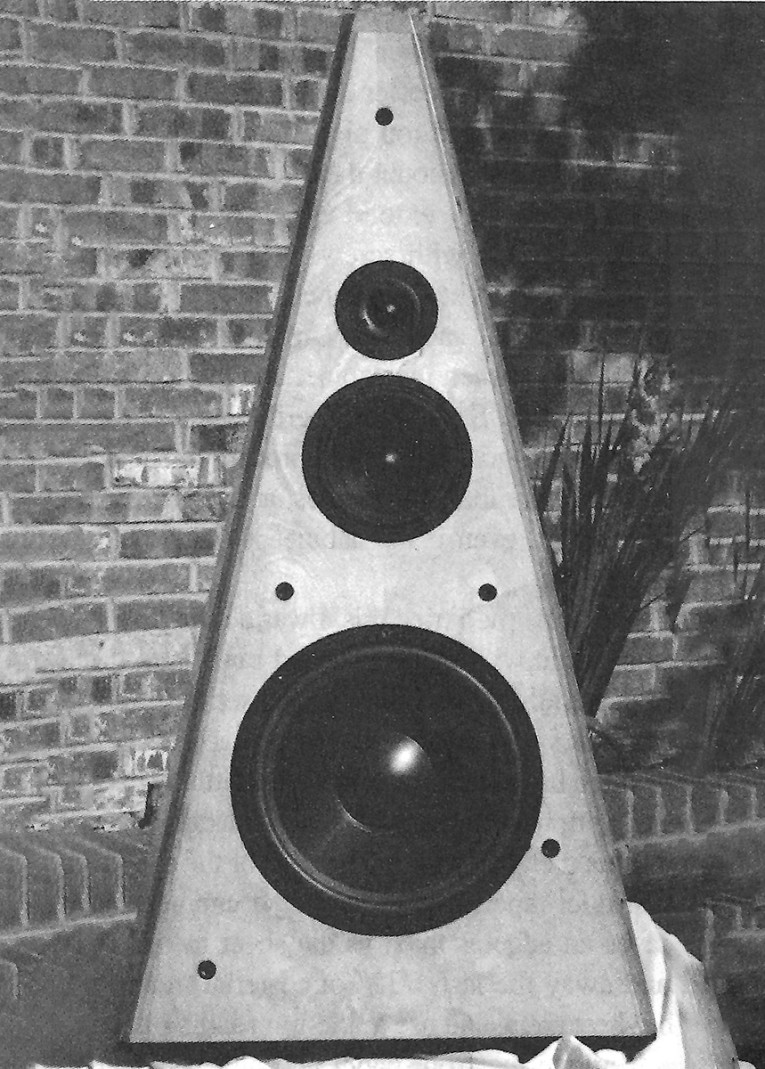
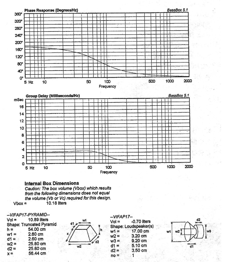
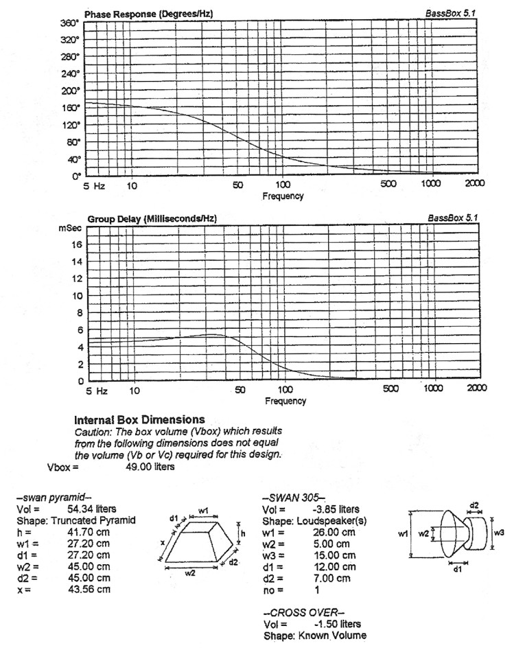
As a last finishing touch to this stage of construction, I chamfered all edges except for the top with a router and a 45° chamfer bit. I sanded the speakers, stained them golden oak, sanded again with 400 grit, and applied two coats of varnish. I decided to paint the bottom flat black, as well as the particleboard visible through the terminal cutout in the back panel. This completes the cabinet construction. Photo 2 shows the front with the grille removed. Figures 10a, 10b, 11a, and 11b are printouts for the woofer and midrange, generated by the design program used (Bassbox 5.1).
The best grille is no grille. That is one of the few things most audiophiles agree on. However, most of us have to consider aesthetics and the curiosity of children and pets. A grille does not need to look boring. One possibility is shown in Photo 1. It is cut from 3/8" plywood, all edges are rounded with a roundover bit, and it is painted flat black.
The fabric should be suitable for this application. Most speaker-component vendors carry an excellent stretch material that is easy to use. I attached it with an electric stapler, covering the staples with black tape. You can attach it to the cabinet with Velcro or ball-and-socket headlocks.
To make sure the balls and sockets match, place the grille frame on the cabinet and temporarily fasten it with tape. With a small drill bit, drill a pilot hole through the grille frame and into the cabinet. Remove the frame and drill a hole of the diameter required to accept the sockets and balls. I used a small amount of hot glue to secure the balls to the frame.
Final Assembly
The first step of the final assembly is to drill the holes required for the terminals and treble controls. Vacuum all chips and dust from the cabinet interior, and inspect all joints to see they are properly caulked. You can use a small mirror to inspect the joints between the front panel and the cabinet side walls. Apply additional caulk wherever you doubt the seal is leakproof. As mentioned before, the cabinet needs to be absolutely airtight, especially the divider between woofer and midrange chamber.
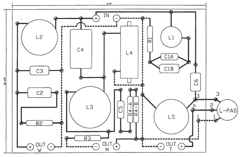
Now prepare the crossover for final installation. Since it is very crowded inside the speaker, it is advisable to install possible prior to crossover installation. Connect sol-der points 1, 2, and 3 on the crossover to the related points, also marked 1, 2, and 3, at the treble-control solder lugs. Prepare cables with lugs on both sides to connect the crossover input posts with the input terminals, and mount them to the input terminals at the crossover.
Prepare the connection cables between the crossover and the woofer. These cables have lugs on one end, and you solder them to the woofer terminals at the other end. Mount the lug end to the connection posts of the crossover. Attach weatherstripping with adhesive backing to the bottom of the crossover around the edges, and strips through the center of the crossover in both directions. Insert the crossover through the woofer opening, and place it approximately in the center of the bottom of the cabinet. Attach with eight 1 ¼" particleboard screws.
Install the treble-control potentiometer. Unfortunately, the shaft of most such controls is only ¾" long, so there is no space for the nut that comes with the controls. I attached the controls with hot glue. Run a bead of glue around the circumference of the control body to make sure it is installed airtight. Take care, however, that the glue does not spill into the potentiometer.
Now install the terminals. Make sure the cable hole is in position vertically to allow easy installation of the cables connecting the speakers with the amplifier. I used a small screwdriver to hold the terminals in position while tightening the nuts on the inside. Hook up the cables from the crossover input posts to the terminals. Make sure the polarity is correct. Install the second nut with a lock washer to make sure it will not come loose.
Attach the midrange and treble cables to the crossover connection posts. Use lock washers, tooth washers, or self-securing nuts to make sure the connections will not come loose.
Damping Material
Now it is time to fill the cabinet with damping material. A wide variety is available for this purpose, such as rockwool, polyester fiberfill or batting, and sheep wool or cotton (make sure the sheep wool is treated with moth repellent). Whatever you are using, it is most important not to overstuff the cabinet or compress the filling. Use the filling material to keep the cables away from the cabinet walls to avoid rattling noise.
To keep the filling away from the woofer cone, cut a piece of fabric with all sides approximately 2" larger than the size of the woofer chamber. The material used for the front cover is a good choice. Poke a hole in the middle of the fabric, and run the cables for the woofer through the hole. Distribute the fabric evenly, so that the filling material is covered, and fasten the fabric with a few staples to the inside wall of the cabinet to keep it in place.
Proceed in the same way with the midrange chamber. Most likely, you will not be able to use the stapler in the midrange chamber. In this case it should be sufficient to push the fabric in between the filling and the cabinet walls. I tested the speaker for a couple of weeks before disassembling it to sand, stain, and varnish it. I found the fabric to be in the same position as originally installed.
Install the gaskets for all drivers using thin (1/8") weatherstripping with self-adhesive backing. Do not overlap the ends, but make sure they butt against each other. Solder the cables to the drivers, making sure the polarity is correct, and position the drivers in the mounting holes. Be especially careful when soldering the tweeter. The voice coil uses very thin wire, and the terminals are very delicate. If you are not sure about your soldering skills, use solderless crimp connectors, which are also an acceptable choice for the other drivers.
The easiest way to fasten the drivers is with particleboard screws. McFeely's has some nice black square-drive screws. I used Allen screws and T-nuts, which somehow seem to look more professional. They are doing a good job for the woofer, but did not work as well for the midrange and tweeter, since they are a lot smaller, and the T-nuts tend to break out of the particleboard. I recommend using pan-head particleboard screws for the midrange and tweeter. Do not use flat-head or countersunk screws for them, since their conical shape will tend to break the tweeter flange and deform the basket.
Tighten the screws in a crossing pattern, as you would tighten the nuts on the wheels of your car, and do not overtighten them, which could deform the driver baskets. When you suddenly find yourself exerting more force to further tighten the screw, the gasket is fully compressed and you should stop. Check the screws about one or two weeks after assembly. By this time, the gasket has fully settled, and the screws might require a little retightening. If you are using a grille, install it, and you have completed the construction.
Tweaking The Speaker
After all the time, labor, and money you have invested to build these speakers, you should not just "hook them up and get them playing." Your existing stereo system, the cables between the amp and speakers, and, most importantly, the positioning of the speakers in the room will have a tremendous effect on the final result.
You have used good-quality cable to construct the crossover and to wire the speakers in the cabinet. The cables from the amp to the speakers should be of the same quality. Keep them as short as possible, and make the left and right channel the same length. Be certain the polarity of the cables is correct.
The room will also have quite an influence on the sound of your new speakers. Try to keep them at least three feet away from any wall. A 12" woofer produces a lot of low-frequency sound, and they are boosted by the surrounding walls-about 3dB in front of a wall, and about 6dB in a comer. In my living room, I placed the speakers about two feet from the back wall and three feet from the side wall. The bass was clean, deep, tight, and precise, and the transient response was good.
We tested the speakers in the apartment of a friend of mine, where it was necessary to place them right in front of the back wall, and, unfortunately, one of them in a comer. In consequence, the bass became overwhelming and muddy. In such a case, you might need to increase the stuffing in the woofer chamber or reduce the bass with your amplifier controls.
Midrange And Treble
The midrange and treble will also be influenced by the location of the speaker in the room-not as dramatically as the low end, but noticeably. In case the speaker is located too close to a side wall, its imaging capabilities will suffer. The ear needs to have a certain delay between the sound wave coming directly from the speaker and the first reflected wave. Although the ear is an amazing instrument, it will become confused and the sound stage will deteriorate if the two wave fronts arrive too close together. You can help this by angling the speaker towards the room's center or by hanging a carpet on the wall close to the speaker.
Every component of your stereo system has its own sound, the room will influence the sound, tastes are different, and the sensitivity of the ear to the different frequencies varies from person to person. To compensate at least a little for these variations, rather than resort to a fixed L-pad in the crossover, I used the treble-control potentiometer. By experimenting, you will find that some recordings sound best if the treble control is set to one certain position, while you might find that others sound better if you reduce or increase the loudness of the tweeter. It took me about two weeks to find out that to my taste the speakers sound best with the controls set to about 50% of full rotation. My wife prefers a little bit more.
Some might find this a bit laborious, but if you are a serious listener, which has nothing to do with the music you prefer, and you spend a few hours a week listening to music, you will find it very rewarding to experiment with the precise speaker location and the setting of the treble controls.
Final Thoughts
How do you judge your speakers? Frequency response curves are a good start, but they tell less than half the story. These curves are either free-field measurements, done in a nonreflective environment, or done with maximum-length-sequence methods. Your normal listening environment does not even come close to these controlled conditions. There are some old designs around that have terrible flaws regarding frequency response, but they sound astonishingly good.
Transient response is another important measurement. It describes how precisely a driver follows a given signal, and how much uncontrolled and unwanted movement it does on its own until it finally settles back in the normal position of the diaphragm. But perfect transient response does not improve the sound of your speaker if the room is busy bouncing the wave around ten times longer than your speaker needs to settle down.
Don't get me wrong. Frequency- and transient-response measurements are extremely powerful tools for the speaker designer, and have helped us tremendously in understanding and improving sound reproduction. If I had possessed these instruments, I would have included these curves, but I would still add the following remarks.
I am basically using five instruments to judge my designs:
- I own a pair of old Smacks exponential horns, which are my reference in regard to transient response.
- I use a Sony CD3000 headset to get an idea of the midrange, treble, and coloration of a speaker.
- I use a pair of Lowther Classic 200 fullrange exponential horns to see how "dynamic and lively" a speaker sounds, and how good its imaging capabilities are.
- I take time, my ears, and a wide variety of music to judge the strengths and flaws of a speaker
- Last, but not least, I get my family and friends to listen to the speakers. Fortunately, we all have different ears and tastes, and from their various reactions,
- I qualify my own impressions.
Speaker Evaluation
How do my speakers sound? Their cut-off frequency is lower than any of the speakers I possess. The simulated frequency response of the LEAP design shows a -3dB point at approximately 45Hz, and I am positive that the speakers are capable of doing that.
Located about three feet away from the wall in a room about 18' x 15', with furniture and carpet, their transient response is nearly as good as the response of my exponential horns. The calculated Q,c is around 0.7, and the final Q,c should be between 0.7 and, at worst, 0.85, although I have not yet measured it.
The midrange shows very little coloration when compared to the headset. Due to its 6½'' size, the driver used as midrange does not have as good a dispersion as smaller midranges or dome midranges. However, this lessens the impact of the room on the imaging. The price paid for this is a relatively narrow sweet spot.
The treble is very clear and detailed. Tweeters such as the ScanSpeak D2905 are able to reproduce more detail, but they are far more expensive. Listening to the music with the headsets, I think I can identify few details that I cannot clearly recognize through the tweeters. But again, that might be an influence of the listening room. Overall, the tweeter sounds clear and never tiresome, with an astonishing amount of detail.
If you crank up the system, the woofer becomes quite impressive, easily able to generate vibrations in the walls, the flooring, and many things that are not properly fastened. The midrange and highs have no trouble reproducing with good quality at the same level.
Room For Improvement
Would I do anything differently if I ever built the Pyramids again? Absolutely! If you are designing speakers, you are dealing with prototypes. I used a double-layer construction to minimize panel vibration, and this works up to considerable listening levels. However, if you really crank them up, you can feel panel vibrations on the side and back walls. To remedy this, I would install, on the side and back walls, diagonal braces made of ¾" x 2" particleboard scrap pieces.
I would use the Allen screws with T-nuts again for the woofer, but not for the midrange and tweeter. Two of the T-nuts came loose, and I had to cut the screws to remove the speakers. I finally rotated the midrange 45°, closed the holes for the Allen screws with hot glue, and used McFeely's black square-drive panhead screws to install the midranges.
If you are really into experimenting and tweaking, I would recommend installing the crossover outside of the speaker in a small box, and running all cables through the cabinet bottoms. Also, I would probably try a lower crossover frequency for the tweeter-around 2.5kHz-to see if this further improves the speaker's imaging capabilities.
I would start with a crossover assembled with lower-cost components and then experiment with more costly ones to see if they really make a difference. If you cannot hear any difference, it is not worth spending the money for the more expensive components. However, your failure to hear any difference might be due to the quality of your stereo system. If you upgrade your system in the future with a better CD-player or amplifier, it might be worth trying the higher-quality components again.
A friend of mine has now built his own pair of Pyramids. He does not possess a router; instead, he cut the side panels 1 1/2'' narrower, which leaves a ¾"x ¾" gap at every edge of the speaker. He then used ¾" oak quarterrounds and glued them to the edges. His speakers do look better, since you cannot see the layers of plywood at the edges. If I built them again, I would use his technique.
Would I recommend these speakers to anybody? Yes, indeed, if you are not afraid of a little tricky woodwork, are willing to spend $600 and about 60-80 hours of work, and have the space available to properly position the speakers in your living room. You would then have a pair of speakers that in my admittedly subjective opinion sound as good as any industrial speakers costing twice as much, and that look like speakers of probably three times the price. AX
This article was originally published in Speaker Builder magazine, March 1998.