Author’s Note: Before I begin, I want to detail some of the resources I used for this article. Among my sources for this article, is Noël van Moselvelde, who was a guest at the Audio Discussions #4, which was sponsored by Audio & Techniek [2]. van Mosselvelde had been responsible for tube reliability and quality control at the tube factory of Philips in Eindhoven, The Netherlands, and was considered an authority on tube reliability and life span. Morgan Jones, author of Valve Amplifiers [3] and Building Valve Amplifiers [4], should not need an introduction in these circles — his books on tube design and tube amplifiers should be household items for anyone interested in the matter. I also obtained information from Robert B. Tomer’s Getting the Most Out of Vacuum Tubes [5], a book from 1960 that has recently been reprinted by audioXpress’ parent company, KCK Media. A mini review of that book can be found here.
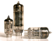
We all know that there are tubes with directly heated cathodes, and those with indirectly heated cathodes. Indirectly heated cathodes have a separate heater structure, often inside a cylindrical cathode, to heat the cathode. The cathode, generally a nickel tube, is covered with several chemical substances like barium and strontium carbonate.
These chemicals are chosen for their ability to emit free electrons at a relatively low temperature, to limit the (losses from) heater power. Combining heater and cathode with all the various compounds in a directly heated cathode structure is, in the end, less effective to emit free electrons than an indirectly heated construction, and will require higher heater power.
The indirect heating is a complex process with chemical reactions and the “number” of free electrons is limited by the end products of the reactions, and when depleted, the tube is at the end of its life. The other mechanism here is increasing interface resistance between the cathode emissive surface and its nickel structure, which will bias the tube.
Heater Voltages
Heaters have a nominal voltage specification, such as 6.3 V (or the 12.6 series) for many dual triodes. How critical is that voltage? What happens when we put it at 6 V? Or 6.5 V? The first obvious effect from too-high heater voltage is that the cathode gets hotter and the emissive material will be reacting faster and evaporating quicker, lowering the tube’s effective life span. Lowering the heater voltage, and thus, the cathode temperature too much will shift the tube’s characteristic down to a lower saturation current and increase distortion.
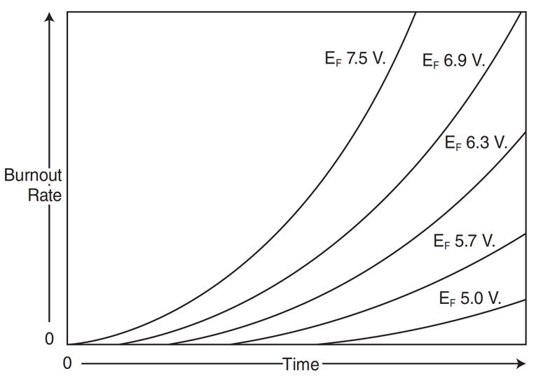
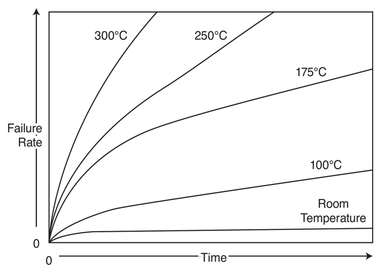
That may not be a problem with low power (pre)amp tubes, but it might be an issue with power tubes. Also, lower temperature cathodes are more sensitive to what is generally called “poisoning” by gas ions present in the tube. Higher (nominal) temperatures provide some protection against poisoning — although it also increases noise. The upshot is that it is inadvisable to lower the heater voltage too far in an attempt to extend tube life even with low anode currents. Nevertheless, lowering heater voltage of a nominal 6.3 V tube to 6.1 V is said to increase tube life by 50% (see Figure 1). [3,5] DC heater power can easily be provided with modern rectifiers and integrated voltage regulators, and it is usually done to avoid power line hum and noise being injected in the amplifier. But DC heater power in itself is detrimental to tube life.
At switch-on, the large inrush currents and the mechanical spiral construction of the heater always cause a very small mechanical movement of the heater structure inside the cathode. With a DC supply, these movements are always in the same direction and of similar magnitude, causing a kind of scraping. Over many switch-on cycles, this scraping can lead to weakening of the isolation between the heater and the cathode, causing crackling sounds and eventually failure. So unless you have an issue with hum, AC powering the heater is better for tube life.
Most heaters today are run from a voltage source, (6.3V or 12.6V are the most common) but sometimes tube heaters are run in a series loop, being current-driven. The older Plxx/PCLxx TV-tubes, for instance, could be run in series directly from the mains, saving a heater transformer. But be careful: Not all heaters have the same thermal mass and/or resistance, so they heat up at different speeds. Unless you carefully balance the loop circuit, it is possible that one heater could heat up more slowly than another, meaning its resistance stays lower than another, and the voltage across the fast-heating one might rise considerably beyond its design value, decreasing tube life.
Last, there is the mains voltage to consider. Both in Europe and the US, mains voltages have steadily risen over the last few decades. In Europe they have risen from 220 V to 230 V or even 240 V, in the US from 110 V to 120 V or even 125 V. That means that, when using vintage power- or heater supply transformers, heater voltages could be, as a matter of routine, 5% to 10% over the nominal value. Needless to say, this will significantly lower tube life expectancy. Use the transformers specified for contemporary mains voltages, or keep the heater voltage in check with small series resistors, if needed.
Although heater failure is far from the most common cause for tube failure, it is still a potential issue and should be considered in tube amplifier design.
Dissipation and Thermal Management
You might think that when the tube has an appreciable dissipation, such as a power tube in Class A, that anode dissipation would also help to heat the cathode so maybe you need less heater power. In principle that is true, but the effect of anode temperature rise on cathode temperature rise goes by the fourth root. So a 100° anode temperature rise effects only has a little more than a 3° rise on the cathode.
On the other hand, cooling the tube or making sure that the environment in which it works doesn’t get too hot has a positive effect on tube life. There are two factors at work here. One is the glass envelope temperature: Glass will always emit gas molecules, which lower the internal vacuum of the tube and may also increase cathode poisoning. Glass out-gassing rises exponentially with temperature so limiting the glass envelope temperature will have a large positive effect on tube life.
Higher glass temperatures also lead to higher temperature gradients at the base pins or top cap, increasing the risk of micro-cracks and leakage (see Figure 2). The other is the anode temperature. A very hot anode can lead to water vapor being released from the mica parts of the tube structure, and this will poison the cathode as well. Making sure that an operating tube has adequate air circulation around it promotes tube life significantly.
Heat It, Then Run It
A point of much discussion is whether it would be a good thing to delay the application of high voltage until the heaters have had time to heat the cathode. There are several mechanisms at work here. In normal operation, the heated cathode emits a cloud of electrons that bunch together at the cathode structure and this cloud is known as the space charge. With anode voltage applied, electrons are attracted to the anode and leave the space charge, which is supplied with new electrons from the cathode. But when the cathode is cold, the space charge is minimal and is rapidly depleted when the anode voltage is present.
Normally, some electrons collide with stray gas molecules, producing ions that are attracted to the cathode. Ions are much more massive than electrons and when they strike the cathode, they can damage the emissive structure and cause small craters—further decreasing the emissive capacity. In normal operation, the space charge will repel these ions but as mentioned, with a cold cathode the space charge is minimal and has much less capacity to limit the ion bombardment on the cathode.
Another phenomenon with a cathode not yet at operating temperature concerns unequal cathode temperature. As the cathode heats up, the temperature will not be uniform and the hotter areas will allow more current than the cooler areas. The current that flows will tend to concentrate in small hot areas, and that will increase the current density to higher values than will be the case at normal operation. That higher current density can locally damage the cathode creating miniature craters in the structure, which overall will have a negative effect on life expectancy.
All these factors suggest that the cathode should be at the operating temperature before the anode voltage is applied. [1] This is especially important when the equipment uses solid-state rectifiers, in which case the anode voltage will be present almost immediately at turn-on. Although there are many amplifiers out there with solid-state rectification that work reliably for many years, it is ultimately a factor in tube reliability deterioration, so a delayed high voltage is a good measure, especially with those more expensive tubes!
Sometimes you read advice that says to keep the heaters on at say half power, to avoid the cold starts, and to avoid high heater inrush current at cold start. Tomer recommends that to significantly extend tube life, although there is of course the issue of higher stand-by power consumption, especially with large installations. [5] But make sure that you don’t actually run the tube with anode voltage and half heater power at the same time — that will surely decrease tube life!
The reverse situation — a heated cathode but no anode voltage to draw cathode current — is equally ill advised. In such a situation, an oxide is formed between the nickel cathode and its emissive layer, generally an oxide of barium and/or strontium. This oxide eventually becomes high resistance, decreasing emission. But it also increases the tube’s shot noise, which can be considered in series with the input signal.
The process is called cathode poisoning. In the days of picture tubes, such poisoning was often removed (or at least attempted to be removed) by briefly running the tube with higher-than-normal heaters and a higher-than-normal anode current, in a process called rejuvenation. But such rejuvenation is generally short-lived.
Superficially, you’d think that a directly heated cathode would be the best solution, as there is no need for a fiddly construction of heater filaments being coiled and rolled up inside a nickel tube. But consider the following: The necessarily fine heater wires have relatively low thermal mass and if you heat them with AC, their temperature would be modulated, ever so slightly, by the line frequency. That carries the risk of hum induction at twice the line frequency as the heating and cooling cycles are related to V2. The heater wires may also, depending on construction details, produce both electromagnetic and electrostatic fields that might modulate the electron stream toward the anode, again risking hum generation.
The solution for these problems is, indeed, coiling the heater inside a tubular cathode structure. It increases the thermal mass of the assembly, limiting thermal mains modulation, and it provides a degree of electrostatic and electromagnetic screening. Thus, the indirectly heated cathode is born.
Heater-Cathode Voltage Difference
In some circuits, such as Series-Regulated Push-Pull (SRPP) or cascode designs, there can be a large potential difference between (one of) the cathodes and its heater. This is always a negative factor, even without a hard short causing flashover. The isolation between the heater wire and the cathode will be lowest with the high temperature of normal operation, and there will always be a certain amount of leakage between the two. The maximum cathode-heater voltage specification is related to how much leakage is allowed, so it is somewhat arbitrary. In any case, higher cathode-heater voltages and increased leakage lead to higher noise levels.
When you heat with DC, the polarity of the voltage difference between the heater and the cathode is important. There are two (conflicting) requirements. If the DC heater is negative with respect to the cathode, electrons emitted by the heater (and there are always a number of them) will flow to the cathode, upsetting the anode-cathode current balance. If you make the heater positive with respect to the cathode, electrons emitted by the cathode on the inside of the cathode tubular structure will flow to the heater.
This will transport material from the cathode to the heater and can lead to a metallic “bridge” between the two and in some cases to a short. But even without this effect, it will, in general, increase cathode-heater leakage and tube noise. For the highest reliability with DC heater power, the general advice is not to make the heater positive with respect to the cathode; yet, some RCA data books recommend that you make the heater positive with respect to the cathode, ideally by 40 V or so, presumably to minimize noise. So as with everything in life, there are tradeoffs.
With an AC heater, the polarity between the heater and the cathode reverses with the mains frequency and that appears to ameliorate some of the effects mentioned earlier. In any case, unless you have insurmountable hum issues, it is best to run the heater on AC.
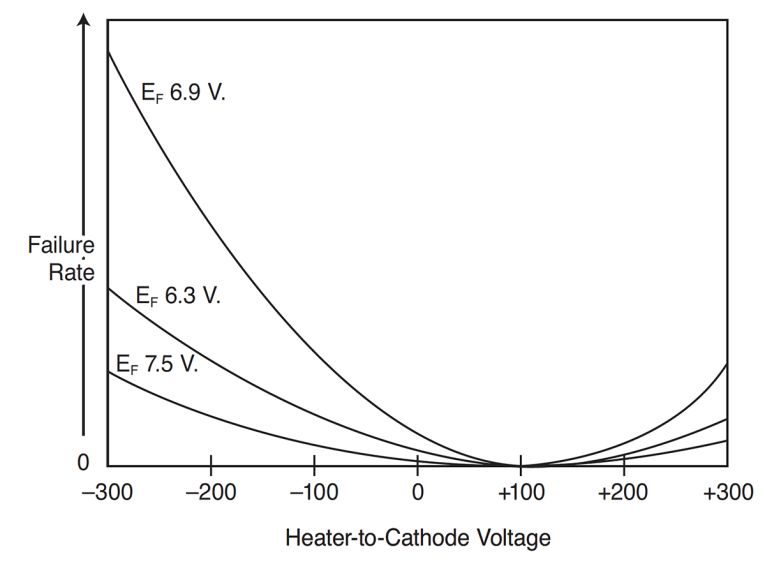
One way to avoid or limit any of the mentioned parasitic currents is to return the heater to ground, or whatever point is selected, via a resistor, to make the leakage (or in case of a short, the shortage) current loop high impedance. The old picture tube datasheets often recommended grounding (or biasing) the heater through a 1M resistor, but in audio amps it can be (much) smaller (see Figure 3).
Coming back to the maximum allowed voltage between cathode and heater, obviously you want to keep it below the datasheet value to avoid flashovers or shorts. But even with voltage differences as low as 30 V and heaters on AC, there can be ionization of remaining gas molecules inside the tube, deteriorating the isolation between cathode and heater — leading to shorts in the long run. If there’s enough current capacity in the circuit, you can get a heater that is “stuck” to a cathode, resulting in a defective tube.
As mentioned earlier, there will be an increase in leakage between the cathode and the heater and increased tube noise long before there is an actual short. It seems a long-term effect though, so only of importance if you want to eke maximum lifetime out of your tube. Although stories abound that a mild mechanical shock to such a tube can separate the heater from the cathode, I have not been able to confirm that.
Grid Current
Power tubes are often operated with positive Vgk, which cause grid current to flow. As long as the tube is designed for that and the drive circuit is low impedance, that’ll be fine. (If the drive circuit is not low impedance, the grid current will cause distortion of the drive signal). Sometimes, you might want to use small signal tubes (e.g., the ubiquitous dual triodes), with very low supply voltages, 50 V or less, and consequently very low Vak.
In those cases the Vgk gets very low too, and even when it doesn’t actually become positive, grid current can start to flow at Vgk more positive than -1 V. You can do that, if you keep the grid current low, but you need to condition the tube for that. The grid surface has all kinds of foreign material, and when grid current starts to flow, this material will be “burned off” so to speak. That means that the characteristics will change during the initial period with grid current. This is one case where burn-in is useful!
Fixed vs. Autobias
Seemingly having no relationship per se to tube life, the choice for biasing method nevertheless has an impact on the probability of tube failure. If a circuit fault develops in a fixed bias circuit, tube current may run away unchecked, leading to tube destruction. With auto-bias, there is always the cathode resistor, providing some amount of negative feedback to limit tube current. A similar issue can arise with fixed screen bias. If in such a circuit the anode voltage collapses due to some failure, the screen will probably start to run red hot, causing destructive gassing, warping of elements, and finally tube failure.
Summary
The above is by no means an exhaustive treatise on tube reliability factors, but it gives an overview of often-discussed issues. If you want to know more about factors determining tube life, Tomer’s book would be a good read. Audio Discussions #4 also has many tips and tricks related to tube life throughout the book. To wrap up the most important points:
• High voltage should preferably be switched on only after the cathode has reached operating temperature, and this is especially important when using solid-state rectifiers.
• To avoid higher anode voltages at switch-off, it is recommended to first switch off the high voltage, then after discharge of the high voltage capacitors, switch off the heaters. This may depend on the actual equipment, possibly thermal inertia of the anode structure is enough to discharge the high voltage capacitors while the anode current peters out. Here is one case where excessive rectifier filter capacitance is a disadvantage.
• The preferred heater supply is AC, unless there is an insurmountable hum issue. Heater voltage should be nominal or a bit lower like -5% for maximum tube life. Consider running the heaters at 50% in standby, never turning them off, to avoid turn-on current surges and insure quick turn-on of the equipment.
• Make sure that an operating tube has sufficient air circulation around the envelope to avoid high temperatures. The tube will get hot, but the surrounding air should not, and should be able to flow unobstructed.
• Keep an eye on heater-cathode voltage differences — even below the specified limit, leakage and noise may increase. If you do switch the heaters completely off, consider limiting heater turn-on surges with an NTC resistor or something similar. But consider where to mount it — an NTC under the chassis may generate enough heat to cause reliability issues on itself. When debating the use of fixed or auto bias for the grid and the screen, also consider the impact on equipment reliability. aX
Author Acknowledgements: I wish to thank Stuart Yaniger, tube aficionado and prolific contributor to audioXpress; and Morgan Jones, purveyor of fine books on all things tube, for their advice and for keeping me on the straight and level. Valuable tips and information were also provided by Menno Vanderveen of ir. bureau Vanderveen, and by Guido Tent of Tentlabs and Grimm Audio. I thank Guido Tent for making Audio Discussion #4 (Reference 2) available. Any remaining errors in this article can safely be attributed to my stubbornness.
This article was originally published in audioXpress, August 2020.
 About the Author
Jan Didden has written for audioXpress since the 1970s and he is the magazine’s Technical Editor. He is retired following a career with the Netherlands Air Force and NATO. He worked in logistics, air defense, and information technology. Retirement has provided him with the time to finish all the audio projects that have piled up for decades. He sometimes writes about them on his website linearaudio.nl. Didden is also known as the publisher and managing editor of the twice-yearly bookzine Linear Audio.
This article was originally published in audioXpress, August 2020.
References
[1] J. Didden, “Tube High-Voltage Delay,” audioXpress, October 2019
[2] “Audio Discussions #4, Audio & Techniek, Rotterdam, The Netherlands, 1991 [The journal Audio & Techniek no longer exists, but some of the participants in this discussion are still active in audio: Guido Tent, of Tentlabs and Grimm Audio; Eelco Grimm of Grimm Audio; and Peter van Willenswaard of Audio Magic, to mention a few. Quoted with permission.
[3] M. Jones, Valve Amplifiers, 4th Edition, Newnes 2012.
[4] M. Jones, Building Valve Amplifiers, 2nd Edition, Newnes, 2014.
[5] R. B. Tomer, Getting the Most Out of Vacuum Tubes, Howard W. Sams & Co., 1960, reprinted by KCK Media Corp., 2019, available at www.cc-webshop.com.