Cooling for this driver is exclusively provided by the motor mass, which is substantial given the large 80mm diameter (8mm thick) neodymium (neo) ring magnet that powers both the high-frequency and low-frequency units, plus the 14.5mm thick milled front plate for the woofer gap and the 3mm thick milled back plate for the compression driver gap. There is also an aluminum shorting ring (Faraday Shield) that contributes to the motor mass, but no vents are required for the 200W continuous power handling rating given by B&C Speakers to the 6.5” woofer section of the 6CNX36, which is impressive for a small diameter driver such as this.
Diaphragm materials for the 6CXN36 include a curvilinear paper cone with a front-side waterproof coating for the woofer, and a high temperature (HT)) polymer for the compression driver diaphragm. The woofer is suspended by a pleated three-roll coated cloth surround, and a 3.5” diameter flat cloth spider. Driving the cone assembly is a 34mm (1.3”) diameter voice coil with glass fiber former wound with round copper wire.
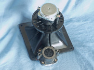
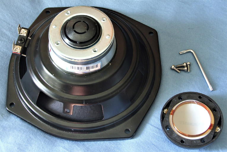
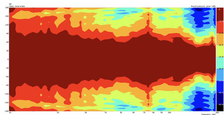
The compression driver has a 36mm (1.4”) diameter voice coil wound on a Kapton former, but wound with aluminum wire. This HT polymer diaphragm fires into a short 90° aluminum conical shaped horn. Figure 1 shows the directivity plot of the compression driver/conical horn, which brings the sensitivity to 100dB, with a recommended crossover frequency of 2kHz. Terminals for the compression driver are located on the injection-molded diaphragm cover on the back of the motor structure and on the frame for the woofer (Photo 2). Applications for the 6CXN36 are primarily as a PA fill driver for small or separated spaces such as under balconies, or as a personal stage monitor.
Testing began with the woofer half of this coax driver using the LinearX LMS and Physical Box IMP Box (the same type voltage/current fixture as a LinearX VIBox) to create both voltage and admittance (current) curves. The driver was clamped to a rigid test fixture in free-air at 0.3V, 1V, 3V, 6V, 10V, and 15V with an oscillator on time between sweeps to simulate the actual thermal process over time. The 15V curves were too nonlinear to get a sufficient curve fit and were discarded. Following my established protocol for Test Bench testing, I no longer use a single added mass measurement and instead use the company supplied Mmd data (9.2 grams for the 6CXN36).
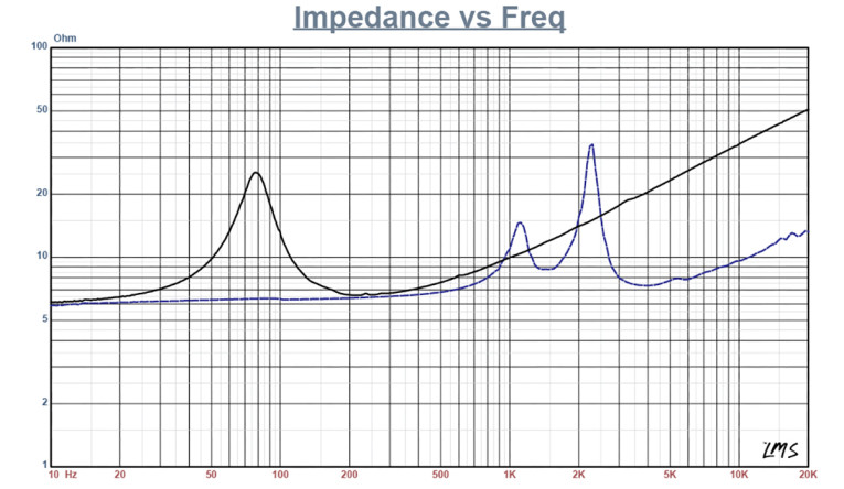
The collected data, in this case the 10 550-point (0.3V-10V) sine wave sweeps for each B&C Speakers sample, were post-processed and the voltage curves divided by the current curves to generate impedance curves, with the phase derived using the LinearX phase calculation method. That data, along with the accompanying voltage curves, was imported to the LEAP 5 Enclosure Shop software. Figure 2 shows the woofer’s 1V free-air impedance curve, along with the compression driver impedance curve. Table 1 compares the LEAP 5 LTD/TSL TSP data and factory parameters for both of B&C 6CXN36 samples.
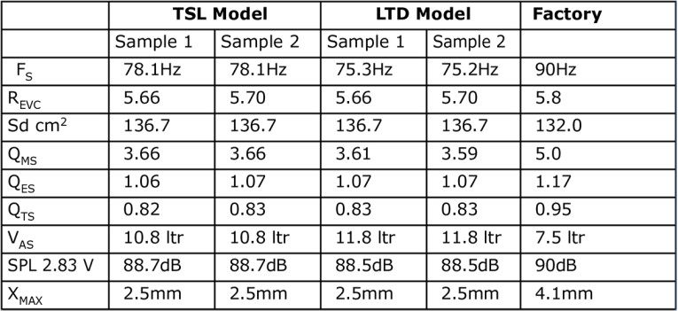
Parameter measurement results for the 6CXN36 were reasonably close to the B&C Speakers factory data, except for the Fs and the Xmax numbers. The Xmax differs only because B&C Speakers, as with a number of other manufacturers, includes fringe field compensation in their Xmax number. I went ahead and programmed the factory Thiele-Small (TS) parameters into LEAP 5 and the result was about 1dB different from my measurements, so close enough.
Since everything looked reasonably good, I proceeded to set up two computer enclosure simulations using the LEAP LTD parameters for Sample 1. This produced a sealed Chebychev Qtc=1.1 alignment box with a 0.35 ft3 volume and 50% fiberglass fill material, and a vented Chebychev/Bessel alignment with a 0.63 ft3 box volume tuned to 58.4Hz, and with 15% fiberglass fill material.
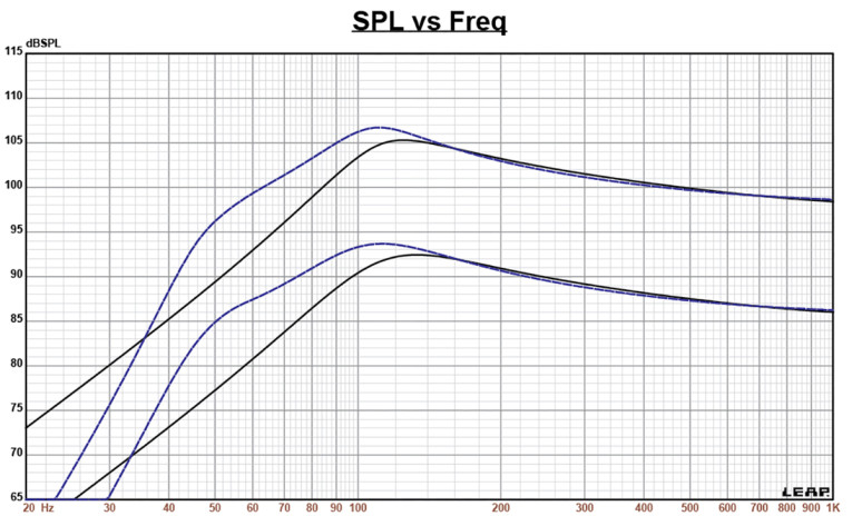
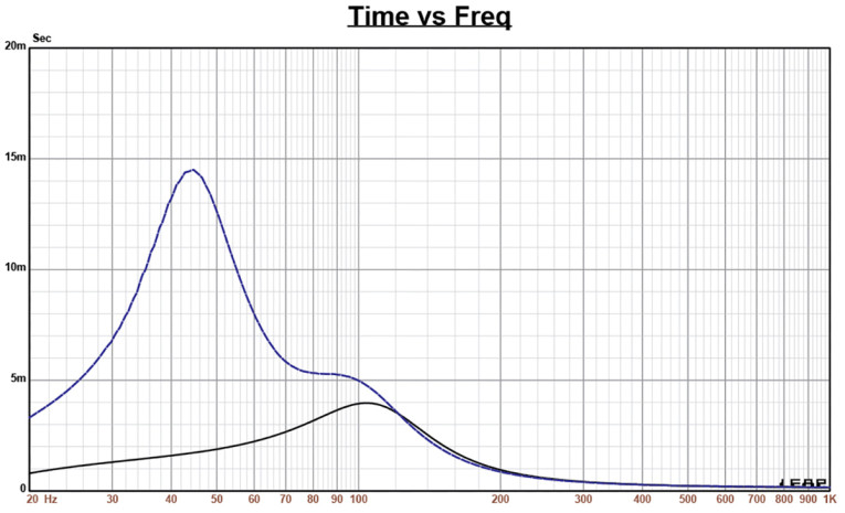
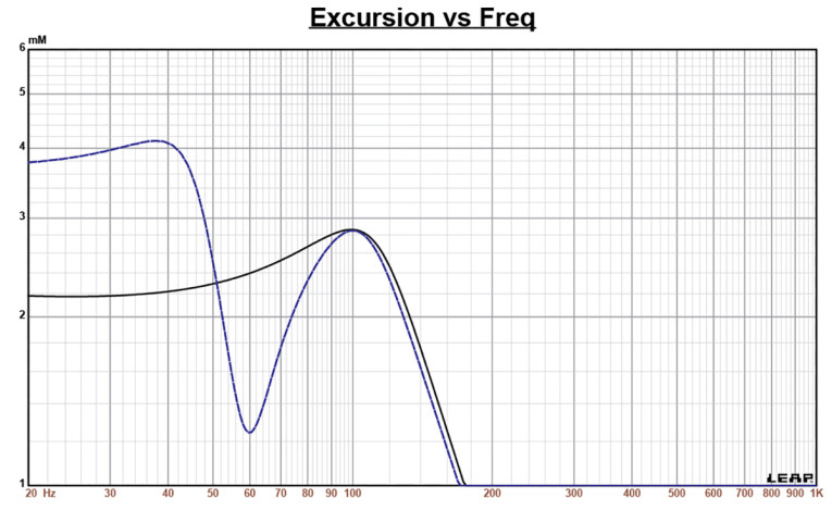
Figure 3 displays the results for the B&C Speakers 6CXN36 woofer in the sealed and vented enclosures at 2.83V and at a voltage level sufficiently high enough to increase cone excursion to Xmax + 15% (2.87mm for the 6CXN36). This produced a F3 frequency of 93Hz (-6dB=79Hz) for the closed enclosure with a Qtc=1.1 (a point of minimum excursion and maximum power handling), and a –3dB = 78Hz (-6dB=61.3Hz) for the vented box. Maximum linear excursion (Xmax + 15%) resulted in 105dB at 13V for the sealed box simulation and 107B at the same 13V input for the vented enclosure. Figure 4 shows the 2.83V group delay curves and Figure 5 shows the 13V excursion curves.
Klippel analysis for the B&C Speakers woofer half of the 6CXN36 was performed at Warkwyn by Jason Cochrane using the Klippel KA3 modular analyzer (as mentioned previously, I will be splitting the Klippel analysis between Redrock Acoustics and Warkwyn).
The Bl(X) curve for 6CXN36, shown in Figure 6, is moderately symmetrical and reasonably broad for a small diameter 6.5” driver, but also with a degree of “tilt” and small amount of offset. The Bl symmetry curve in Figure 7 shows less than 0.5mm forward offset once the graph reached a place of certainty at the 2.5mm Xmax point, falling to nearly zero offset by 4mm.
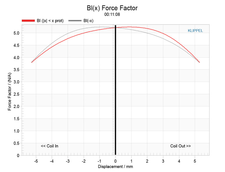
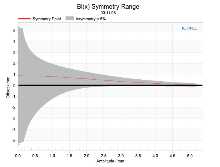
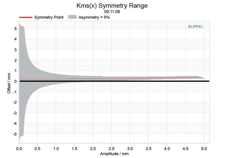
Figure 8 shows the Kms(X) curves and Figure 9 shows Kms symmetry curves for the 6CXN36 coax. The Kms Stiffness of Compliance curve (Figure 8) is also broad and symmetrical and with a small amount of offset. The Kms symmetry range curve (Figure 9) indicates a near trivial 0.24mm forward offset at the 2.5mm Xmax point, and does not vary much through the entire range of this transducer’s excursion profile.

Displacement limiting numbers calculated by the Klippel analyzer for the using the full-range woofer criteria for Bl was XBl @ 82% (Bl dropping to 82% of its maximum value) was 4.46mm (slightly greater than the B&C Speakers Xmax for the 6CXN36) for the prescribed 10% distortion level. For the compliance, XC @ 75% Cms minimum was only 3.2mm, which means that for the B&C Speakers woofer section of this coax driver, the compliance is the more limiting factor for getting to the 10% distortion level. However, both numbers exceed the 2.5mm physical Xmax of this driver.
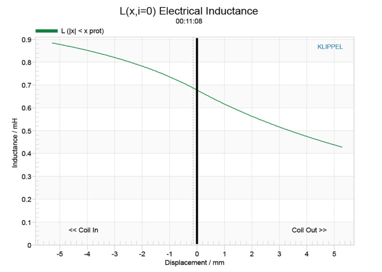
Figure 10 gives the inductance curves Le(X) for the 6CXN36. Inductance will typically increase in the rear direction from the zero rest position as the voice coil covers more pole area, which is what is happening here, typical of this type of neo motor that incorporates an aluminum demodulation (shorting) ring. The maximum inductance swing for this driver from Xmax in to Xmax out is a low 0.26mH, which is good performance for this coax (woofer and compression driver) neo motor.
With the Klippel analysis completed, I proceeded to mount the B&C Speakers 6CXN36 in an enclosure, which had a 12” × 7” baffle, filled with foam damping material. Then, I measured both the woofer and the compression driver on- and off-axis from 200Hz to 40kHz at 2V/0.5m, normalized to 2.83V/1m using the Loudsoft FINE R+D analyzer and the GRAS 46BE microphone (courtesy of Loudsoft and GRAS Sound & Vibration).
Figure 11 gives the B&C Speakers 6CXN36 woofer’s on-axis response along with the compression driver’s on-axis response. The woofer has a gently rising response out to 5kHz, where it begins a typical second-order low-pass roll-off beginning with no serious anomalies. For the compression driver, the response extends from 1.2kHz out to 20kHz, with some substantial undulations along the way, but smooths out significantly as you measure off-axis.
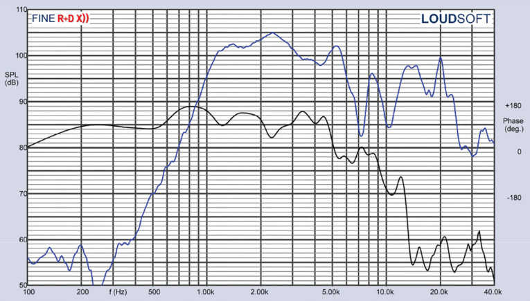
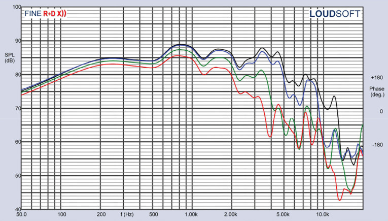
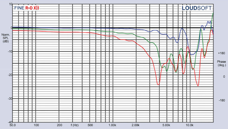
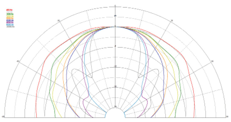
Figure 12 depicts the woofer’s on- and off-axis frequency response at 0°, 15°, 30°, and 45° degrees. The -3dB at 30° with respect to the on-axis curve occurs at 2kHz, which coincides with recommended crossover frequency for the compression driver and conical horn. Figure 13 gives the normalized version of Figure 12. Figure 14 depicts the CLIO 180° polar pot (in 10° increments). And last, Figure 15 gives the two-sample SPL comparisons for the 6CXN36 woofers, both samples matched within 0.5dB to 1.5dB, which is within the woofer’s operating range.
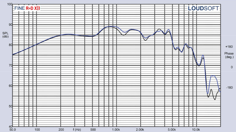
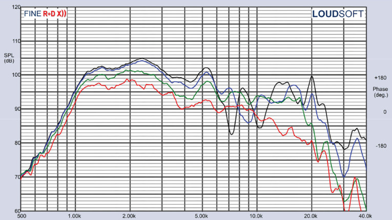
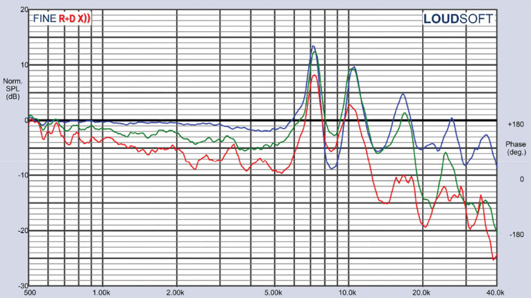
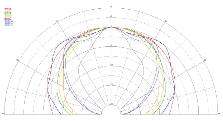
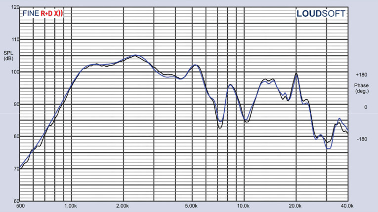
For the compression driver, Figure 16 gives the on- and off-axis horizontal frequency response out to 45°, with the normalized version shown in Figure 17. Figure 18 shows CLIO 180° polar plot (processed in 10° increments). Figure 19 depicts the two-sample SPL comparison for the compression driver half of the 6CXN36 coax, which is within 0.5dB to 2dB above 2kHz.
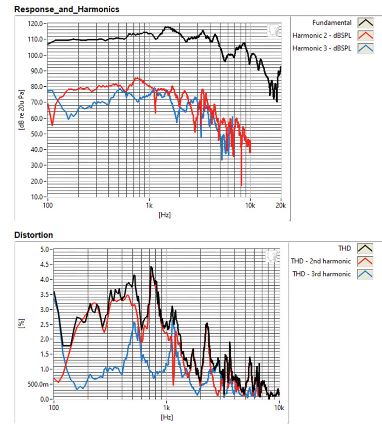
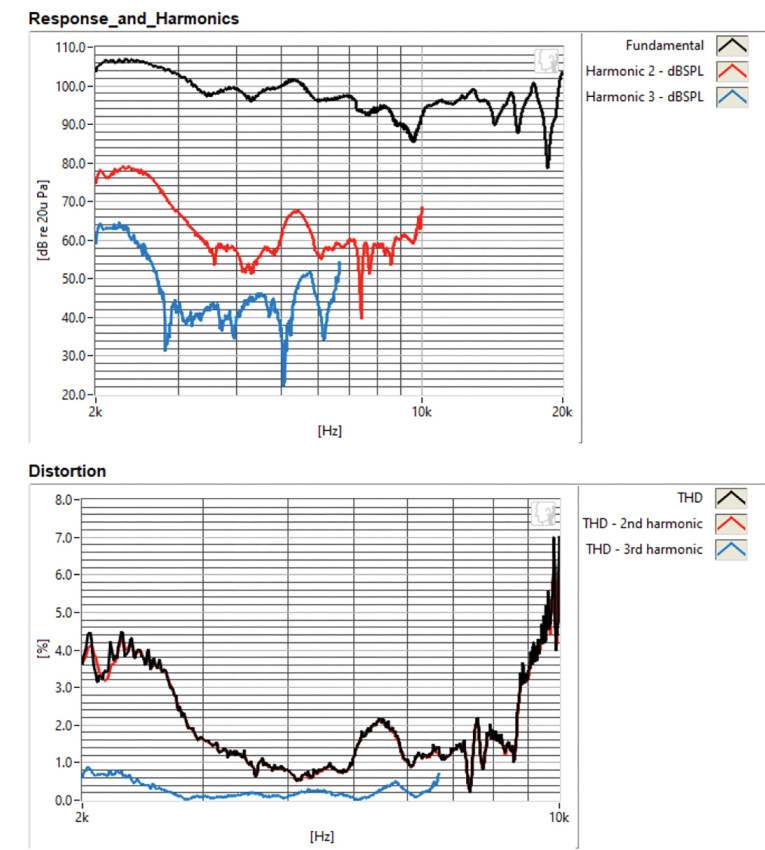
The final group of tests was performed using the Listen, Inc. AmpConnect analyzer and the SC-1 microphone (courtesy of Listen, Inc.) along with the SoundCheck software to measure distortion and generate time frequency plots. Setting up for the distortion measurement consisted of mounting the driver rigidly in free-air, and setting the voltage level determined to raise the SPL to 94dB for the woofer (104dB for the compression driver) at 1m using a pink noise stimulus. Then, I measured the distortion with the Listen microphone placed 10cm from the woofer dust cap and tweeter horn. Figure 20 shows the distortion curves for the woofer (7.4V), and Figure 21 shows the distortion curves for the compression driver (4.5V).
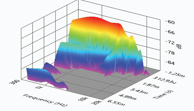
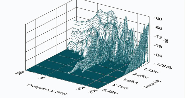
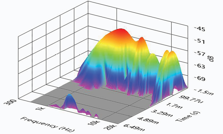
With the distortion test completed, I set up SoundCheck to produce a 2.83V/1m impulse response for both the woofer and the compression driver and imported the data into Listen’s SoundMap Time/Frequency software. Figure 22 shows the resulting cumulative spectral decay (CSD) waterfall plot for the 6CXN36 woofer. Figure 23 shows the CSD plot for the compression driver. Figure 24 gives the Wigner-Ville logarithmic surface map for the woofer, and Figure 25 displays the Short Time Fourier Transform (STFT) for the compression driver.

With all this data taken together, the 6CXN36 is a well-designed and cost-effective pro sound coax. B&C Speakers’ products are consistently well engineered with good performance characteristics and trade-offs, with the 6CXN36 representing another good example of the company’s craft. For more information, visit www.bcspeakers.com. VC
This article was originally published in Voice Coil, November 2022