Obviously the engineering team at SEAS was keenly aware of this issue in woofers as well as the rear reflection problem in tweeters where the motor has a pole piece directly behind the dome diaphragm that causes a similar reflection issues. Both these problems led SEAS to develop its patented Hexadym radially charged magnetic motor structure, US Patent 6,020,805 (filed in December 1998 and granted in December 2000). Looking at the diagram from the patent shown in Figure 1, you can see that the motor structure is made of a series of rectangular neodymium (neo) magnets arranged in a hexagonal six-sided pattern around the voice coil of the motor.
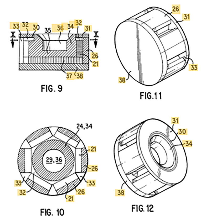
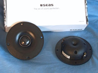
Given the physical layout, these neo magnet parts are charged sideways, or radially to focus flux into a gap area. Incorporated in a tweeter motor, this means it is possible to utilize a substantially hollow pole piece that produces significantly less reflection back into the dome diaphragm. SEAS currently uses its Hexadym technology in four of its high-end Excel line tweeters: the T25CF002, which was the original Millennium model to use the Hexadym motor; the T29CF002 Crescendo 29mm soft dome tweeter: and the two diamond diaphragm Hexadym motor tweeters, the T29D002 and the T29D002. Removing the harsh pole piece rear reflections underneath a tweeter diaphragm substantially increases the subjective perceived sense of detail in the upper harmonic range.
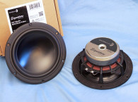
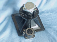
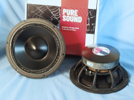
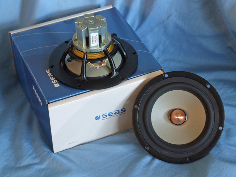
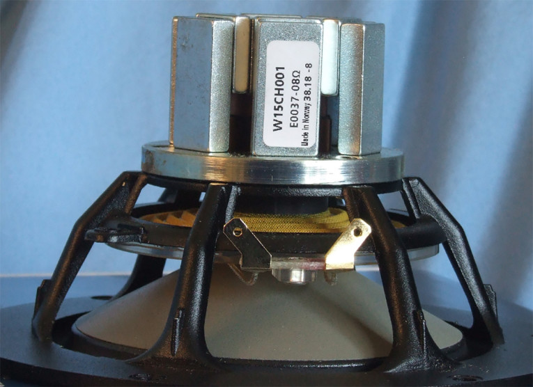
The second important application of the SEAS Hexadym motor structure was used in the subject of this Test Bench explication, the SEAS W15CH001. While woofers don’t suffer from the pole piece reflection issue that is common in tweeter design, they do have a reflection problem caused by the frame and the motor structure. In terms of frame reflections, it is currently the state of the art to produce woofer frames with minimally wide spokes that connect to the motor system. Looking at Photo 1 and Photo 2 of the W15CH001, it is obvious that the frame spoke width and shape have been optimized to minimize reflections back into the cone (this also includes the spider mounting shelf). The out-of-the-box leap made by SEAS with the W15CH001 was to incorporate the Hexadym motor technology to almost completely eliminate the reflections off the motor structure that is common in the majority of woofers and midrange drivers. This enhancement, like the reduction of the pole piece reflections in a tweeter, substantially reduces the “clutter” caused by motor reflections and result in increased perceived musical detail.
Besides the rear reflection reducing technology incorporated into the frame design and Hexadym motor structure of the SEAS W15CH001, this driver has a number of other important features. The cone assembly features a high purity cast, machined and surface-treated magnesium cone that is extremely stiff and well damped. Compliance is provided by NBR surround and treated 2.5” diameter cloth flat spider (damper).
The Hexadym motor structure incorporates a T-shaped pole piece with dual copper shorting rings (Faraday shields), a solid copper phase plug that enhances the shorting ring performance, a 26mm diameter voice coil wound with round copper wire terminated to a pair of solderable gold terminals, plus a fairly robust (for a 5.25” driver) 200W short-term power handling capacity. For cooling, the frame is completely open beneath the spider mounting shelf, and with no pole vent. However, as you can see in Photo 2, one of the benefits of the Hexadym motor layout is—as with the Scan-Speak AirCirc motor—the substantial amount of venting from the inside of the motor structure for cooling the voice coil assembly.
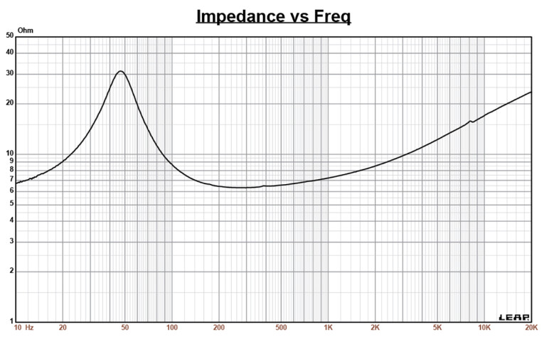
Testing began with the driver clamped to a rigid test fixture in free-air, and using a LinearX LMS analyzer and Physical Lab Imp Box produced both voltage and admittance (current) curves at 0.3V, 1V, 3V, 6V, and 10V (each sweep with the appropriate 200Hz tone played between sweeps to progressively heat the voice coil to mimic actual operating conditions). The 10V curves were close to making a useful curve fit, however I discarded them and post-processed the remaining eight 10Hz to 20kHz 550-point stepped sine wave curve pairs for each sample. I divided the voltage curves by the current curves creating the five impedance curves. The impedance curves each had the LMS phase calculation procedure applied and, along with the voltage curve for each sweep, were imported to the LEAP 5 Enclosure Shop CAD program.
Since most Thiele-Small parameter (TSP) data provided by OEM manufacturers is either produced employing either the standard TS model or the LinearX LEAP 4 TSL model, I also include a LEAP 4 TSL model using the 1V free-air curves (Figure 2). I selected the complete curve set, the multiple voltage impedance curves for the LTD model, and the 1V impedance curves for the TSL model in the transducer derivation menu in LEAP 5 and created the parameters for the computer box simulations. Table 1 compares the LEAP 5 LTD and TSL data and factory parameters for both SEAS W15CH001 samples.
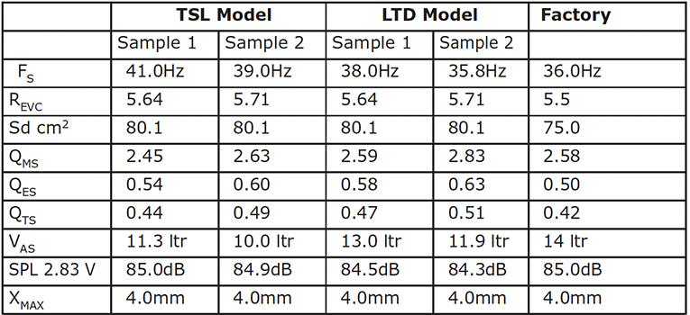
TSP results for the SEAS Hexadym motor 5.25” midbass woofer were rather close to the factory data, with some variance in the Vas and SPL. Part of the variation is due to the difference in Sd calculation, a fairly sensitive parameter. The criteria used for Test Bench is to calculate Sd from the diameter of the cone plus half of the surround width on each side of the cone assembly (the criteria established in LEAP 5). That said, I followed my standard protocol and preceded to program computer enclosure simulations using the LEAP LTD parameters for Sample 1. I used LEAP 5 Enclosure shop to generate enclosure volumes, which resulted in a 0.29ft3 sealed box with a Qtc=0.7 and 50% fiberglass fill material; and an vented QB3 type vented alignment with a 0.54ft3 volume tuned to 37Hz with 15% fiberglass fill material.
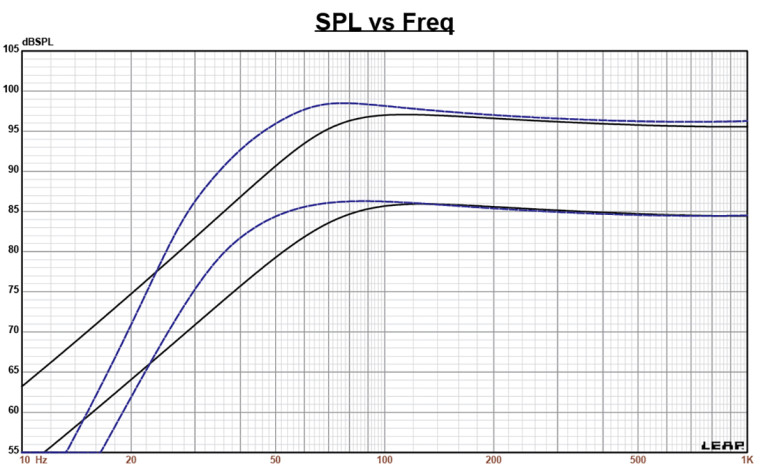
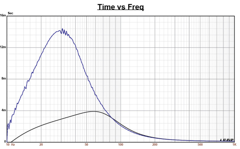
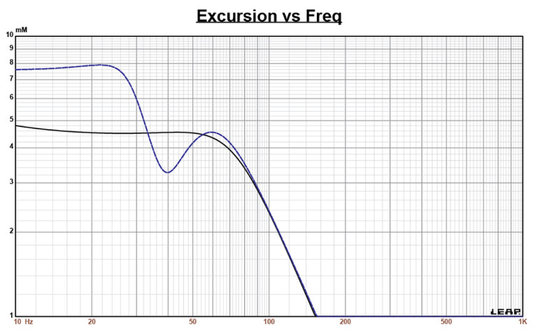
Figure 3 depicts the results for the SEAS W15CH001 in the two enclosures at 2.83V and at a voltage level sufficiently high enough to increase cone excursion to Xmax+15% (4.6mm for the W15CH001). This simulation resulted in a F3 frequency of 65Hz (F6=52Hz) with Qtc=0.7 for the 0.29ft3 sealed enclosure and –3dB=44Hz (F6=37Hz) for the 0.54t3 QB3 vented box simulation. Increasing the voltage input to both simulations until the maximum linear cone excursion was reached resulted in 97dB at 11V for the closed enclosure and 98.5dB at 12V input level for the larger vented box. Figure 4 shows the 2.83V group delay curves. Figure 5 shows the 11V/12V excursion curves.
Klippel analysis for the SEAS W15CH001 produced the Bl(X), Kms(X) and Bl and Kms Symmetry Range plots given in Figures 6-9. This data was produced by Jason Cochrane, of Warkwyn, with the KA3 Klippel analyzer.
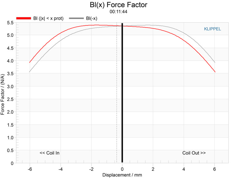
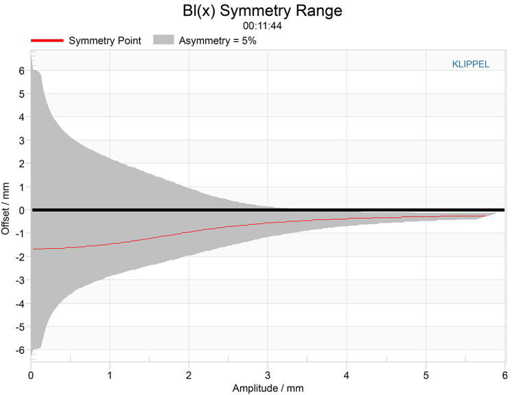
The Bl(X) curve for W15CH001 woofer (Figure 6) is flat, very broad and symmetrical, especially for a 5.25” woofer, and with small amount of tilt and coil-in (rearward) offset. Looking at the Bl Symmetry plot (Figure 7), by the time we get to a point of reasonable certainty at 4mm physical Xmax of this driver, the coil-in offset is a negligible 0.39mm.
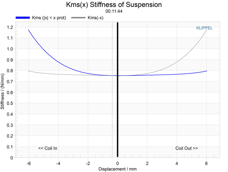
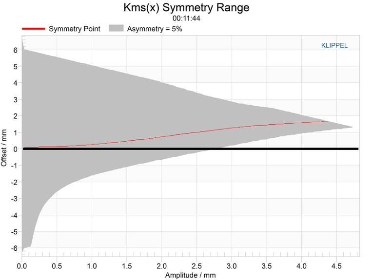
Figure 8 and Figure 9 give the Kms(X) and Kms Symmetry Range curves for the 5.25” midbass driver. The Kms(X) curve does exhibit a degree of asymmetry, with a small amount of both coil-out offset. Looking at the Kms Symmetry Range curve shown in Figure 9, there is 1.6mm coil-out offset at 4mm physical Xmax excursion point.
Displacement limiting numbers calculated by the Klippel analyzer for the SEAS W15CH001 were XBl @ 82% Bl=4.82mm and for XC @ 75%, Cms minimum was 5.1mm, which means that for the W15CH001, the Bl was the limiting factor for the 10% distortion criteria, but both number were beyond the 4mm physical Xmax of the driver, so definitely good performance here.
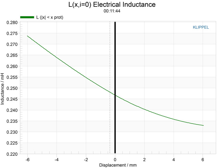
Figure 10 gives the inductance curves L(X) for the W15CH001 5.25” midbass driver. Inductance will typically increase in the rear direction from the zero rest position as the voice coil covers more pole area, which is what we see with the radially charged Hexadym motor. From Xmax out to Xmax in, the inductance range (“swing”) only varies by 0.08mH, which is excellent inductive performance.
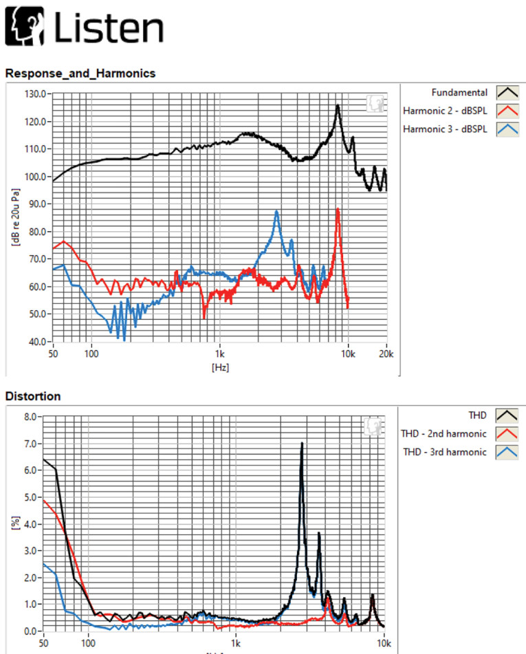
Next I fired up the Listen, Inc. SoundCheck analyzer using SoundCheck 18 software and the AudioConnect interface along with the 1/4” SCM measurement microphone and set it up for distortion measurements (provided courtesy of Listen, Inc.). The SPL at 1m for the 5.25” SEAS woofer mounted in a free-air was set to 94dB (my standard for home audio devices). This required 8.36V. With the microphone placed at 10cm from the dust cap, the W15CH001 produced the distortion curves shown in Figure 11.
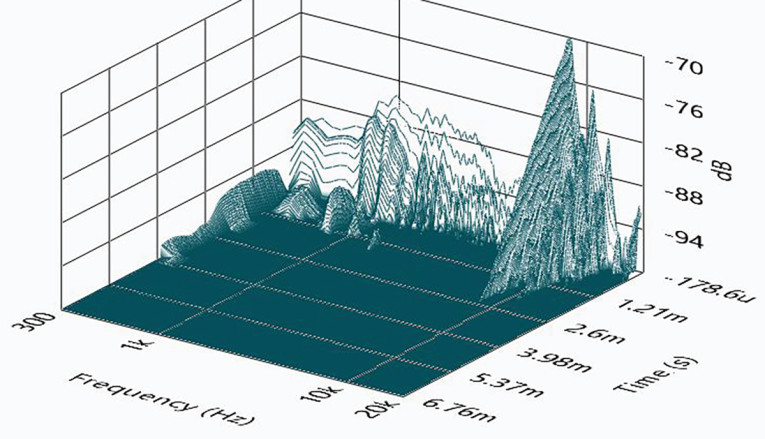
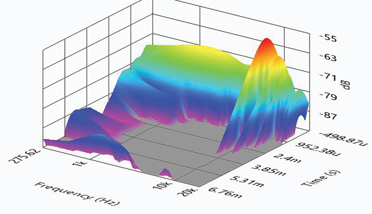
Following the distortion measurements, I mounted the 5.25” SEAS W15 midbass driver in an enclosure with a 12” × 8” baffle and made a 2.83V impulse measurement. This was imported into Listen’s SoundMap software, windowed to remove the room reflections. Figure 12 shows the cumulative spectral decay (CSD) waterfall plot. Figure 13 shows the Wigner-Ville plot.
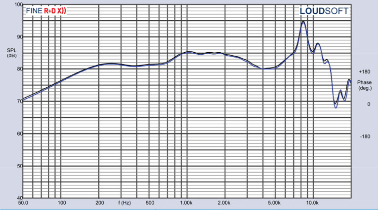
For the remaining series of SPL measurements, using the same enclosure as with the impulse response testing, I then measured the driver frequency response using the Loudsoft FINE R+D analyzer and the GRAS 46BE microphone (courtesy of Loudsoft and GRAS Sound & Vibration) both on- and off-axis from 300Hz to 20kHz with a 1/6 octave smoothing (to simulate the 100-point LMS resolution used for years in this column) at 2.83V/1m using the cosine windowed FFT method. Figure 14 depicts the W15CH001 on-axis response, yielding a relatively smooth rising response from 300Hz to 4kHz, followed by the magnesium break-up mode peak centered on 8.2kHz.
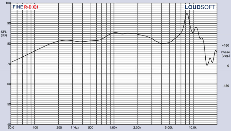
Figure 15 illustrates the on- and off-axis frequency response at 0°, 15°, 30°, and 45°. The -3dB at 30° with respect to the on-axis curve occurs at 2.6 kHz, which suggest a likely crossover point of 2.5kHz to 3kHz would be appropriate for the W15CH001. Figure 16 gives the normalized version of Figure 15.
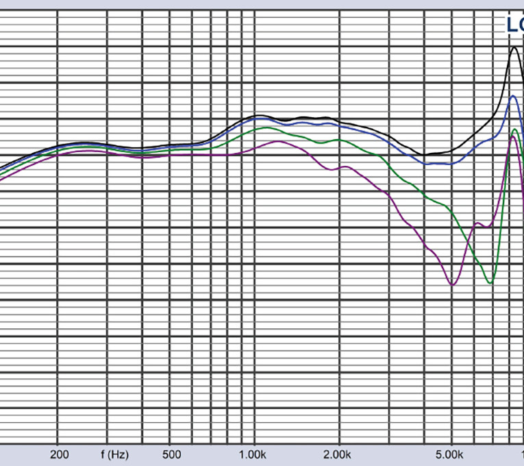
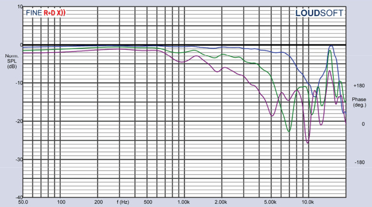
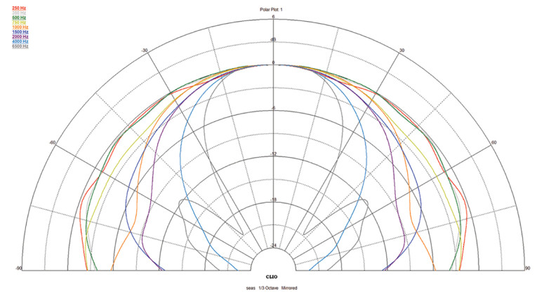
Figure 17 shows the CLIO Pocket (courtesy of Audiomatica SRL) generated horizontal plane polar plot (in 10° increments with 1/3 Octave smoothing applied). And last, Figure 18 gives the two-sample SPL comparisons for the SEAS W15CH001 Hexadym motor driver, showing both samples very closely matched within ±0.25 throughout the operating range of the driver.
As I would expect, the SEAS W15CH001 Excel driver exhibits excellent build quality along with well-thought out design engineering. However, the compact Hexadym motor and the resulting diminished reflections of the small footprint are a significant proprietary accomplishment and an outstanding contribution to the current paradigm of loudspeaker engineering.
I should additionally mention that SEAS also offers a Nextel-coated paper cone midrange driver, the M15CH002, which also incorporates the Hexadym motor structure. Its response range is from about 100Hz to 10kHz, with a characteristic sensitivity of 88.5dB. For more information about these drivers, visit the SEAS website at www.seas.no. VC
This article was originally published in Voice Coil, July 2022