

Intended to be a more hi-fi substitute for 1” compression drivers, the LT6 and all of the other new Radian ribbon high-frequency devices were designed by 35-year loudspeaker engineering veteran Igor Levitsky. Levitsky began designing planar ribbon drivers and speakers in the former Soviet Union in 1986 as a young engineer after graduating from Kiev Technical University in electroacoustics.
Beginning in 1995, Levitsky worked with Hi-Vi Research, where he developed a complete production process for manufacturing ribbon diaphragms. Over the next 20 years, Levitsky developed planar ribbon drivers and speaker systems for the consumer market for BG Radia (acquired by Christie Digital in 2014) and for the pro market with SLS Audio (acquired by Dolby in 2014). Levitsky also worked with OPPO and Dai-Ichi on the development of the award-winning OPPO PM1 and PM3 planar magnetic headphones. He joined Radian Audio Engineering in 2018 with the goal of bringing the latest planar ribbon technology innovations to the pro sound market. Levitsky holds a total of six patents on planar ribbon driver and speaker design.
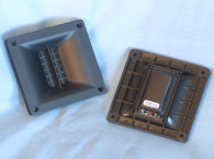
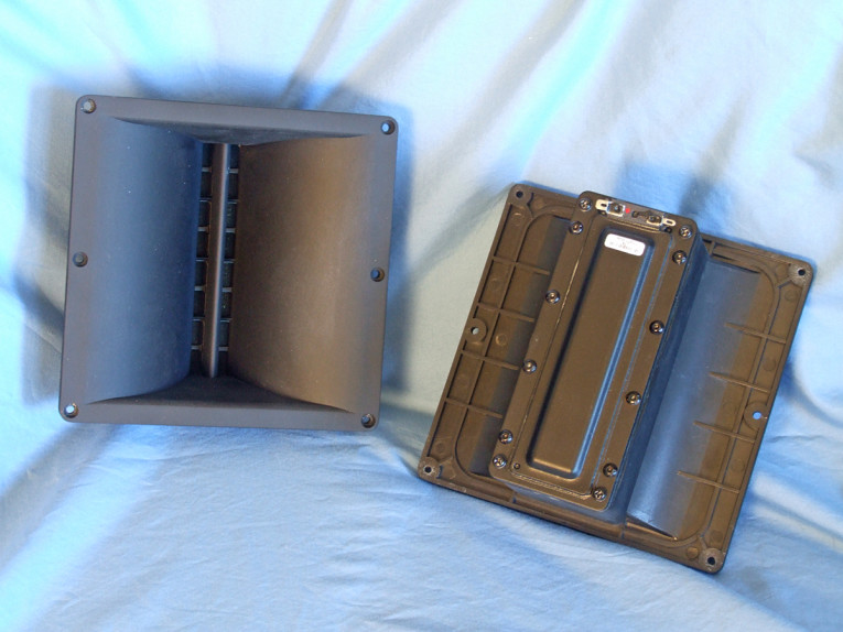
Features for the LT6 waveguide ribbon transducer include a FEA-optimized neodymium magnet motor structure, Kapton diaphragm, a continuous power handling of 40 W AES with a 150 W short-term IEC power handing, a 1.7 kHz to 2 kHz recommended crossover frequency (with a minimum 12 dB/octave high-pass network), and a 1 W/1 m 103 dB sensitivity (average output across the operational frequency range with the LT6 waveguide). The LT6 waveguide directivity is 100° × 40° and is optimized for line arrays.
Testing commenced using the LinearX LMS analyzer to produce the 300-point stepped sine wave impedance plot shown in Figure 1, with the solid black curve representing the LT6 ribbon mounted on the waveguide and the dashed blue curve representing the ribbon without the waveguide. With a nominal 9 Ω impedance, the LT6 has a 7.1 Ω DCR, with minimum impedance mounted on the waveguide of 7.3 Ω and at 2.79 kHz.
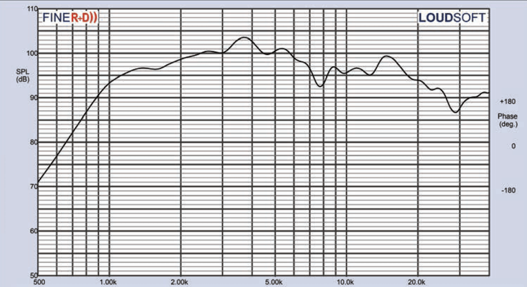
Next, I mounted the LT6 ribbon/waveguide combination with an enclosure that had a 16.5” × 11” baffle and measured both the horizontal and vertical on- and off-axis at 2.0 V/0.5 m (normalized to 2.83 V/1 m) from 0° on-axis to 60° off-axis using the LoudSoft FINE R+D analyzer and the GRAS 46BE microphone (supplied courtesy of LoudSoft and GRAS Sound & Vibration). Figure 2 displays the on-axis frequency response of the compression driver / horn, which is ±5.5 dB with no major anomalies from the 2 kHz recommended crossover frequency to about 22 kHz, beginning its second-order low-pass roll-off at 20 kHz.

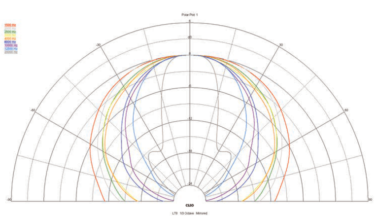


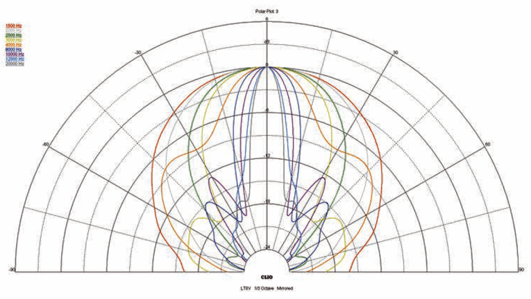
Figure 3 shows the 0°-60° on and off-axis response in the horizontal plane. Figure 4 displays the normalized horizontal plane response. Figure 5 shows the 180° horizontal polar plot (in 10° increments with 1/3 octave smoothing applied), which was generated by the CLIO Pocket analyzer and the accompanying microphone (courtesy of Audiomatica SRL).
For the vertical plane of the LT6 waveguide, Figure 6 gives the 0° to 60° response. In Figure 7 it is normalized. Figure 8 shows the CLIO-generated power plot. Last, Figure 9 provides the two-sample SPL comparison, showing the two Radian LT6 waveguide driver samples to be matched within less than 1 dB or less throughout the entire operating range of the transducer, except for some small areas with 2 dB to 3 dB variations centered on 3.5 kHz and 8.2 kHz.
For the remaining series of tests, I set up the Listen, Inc. AudioConnect analyzer and 1/4” SCM microphone (provided to Voice Coil by Listen, Inc.) to measure distortion and generate time-frequency plots. For the distortion measurement, I again mounted the LT6 waveguide combination in the same enclosure as was used for the frequency response measurements, and set the SPL to 94 dB at 1 m (1.75 V determined by using a pink noise stimulus generator and internal SLM in the SoundCheck 17 software).
Then I measured the distortion with the Listen microphone placed 10 cm from the mouth of the waveguide. This produced the distortion curves shown in Figure 10. Note the extremely low third-harmonic level.
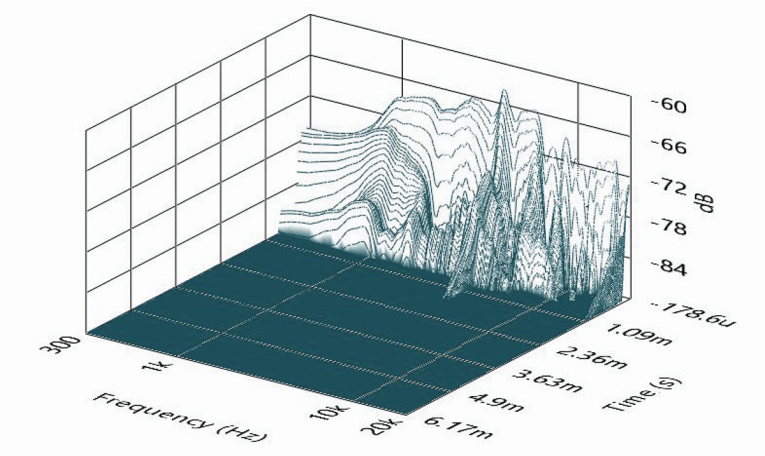
Following this test sequence, I set up SoundCheck 17 to generate a 2.83 V/1 m impulse response curve for this driver/horn and imported the data into Listen’s SoundMap Time/Frequency software. Figure 11 shows the resulting cumulative spectral decay (CSD) waterfall plot. Figure 12 shows the Short Time Fourier Transform (STFT) plot.


After reviewing all the data presented in this explication, the Radian Audio Engineering LT6 waveguide driver is as intended, an interesting substitute for 1” compression drivers, and given the reputation of ribbon transducers for detail and clarity, a great alternative. Combine that with excellent build quality, this driver would provide a viable new choice for studio monitors and PA speakers and PA arrays. For more information about this driver and other Radian Audio Engineering OEM pro sound products, visit www.radianaudio.com. VC
This article was originally published in Voice Coil, June 2020.