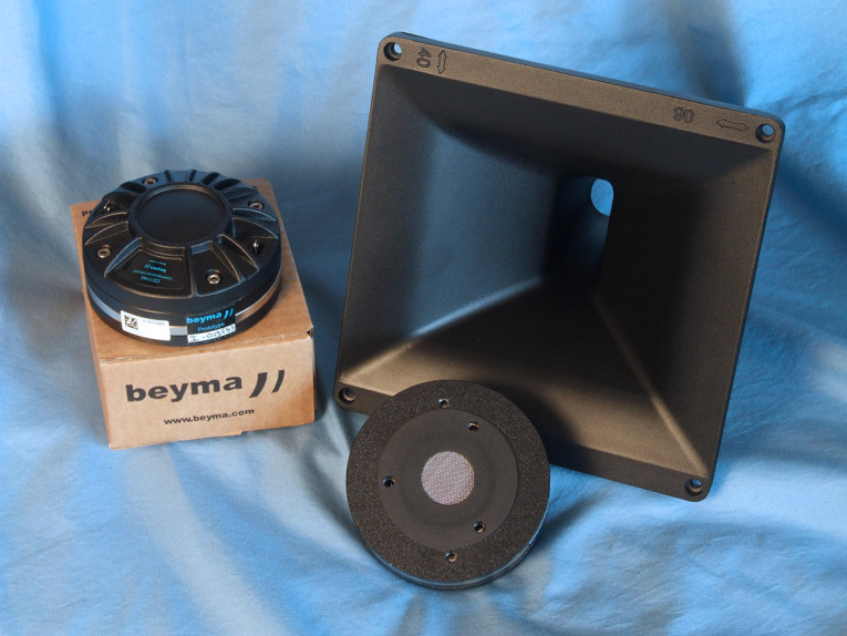
Other features include a FEA-optimized neodymium magnet motor structure, a program power handling of 140W with a 70W AES power handling rating, a 1.5kHz recommended crossover frequency (with a minimum 12dB/octave high-pass network), and 1W/1m 111dB sensitivity (measured on a Beyma TD-164 horn).
The TD-194 horn has a 90° × 40° coverage pattern and is made from cast aluminum. For ease of mounting, the horn is square and the horizontal and vertical orientation is molded into the outer edge. With a 1200Hz cut-off frequency, the TD-194 has constant directivity throughout its operating range with a horizontal and vertical beamwidth of -6dB, 2kHz to 16kHz.
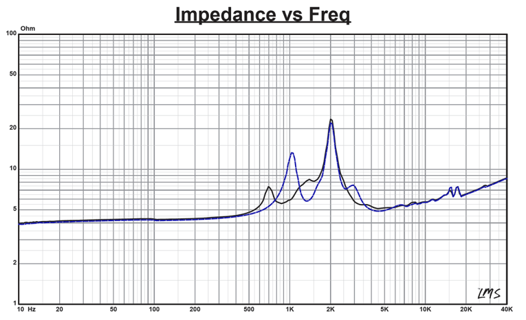
Testing commenced using the LinearX LMS analyzer to produce the 300-point stepped sine wave impedance plot shown in Figure 1. The solid black curve represents the CD-11Nd mounted on the TD-194 horn and the dashed blue curve represents the compression driver without the horn. With a nominal 8Ω impedance, the CD-11Nd has a 4.28Ω DCR, with minimum impedance mounted on the TD-194 horn of 5.11Ω and at 4.6kHz.
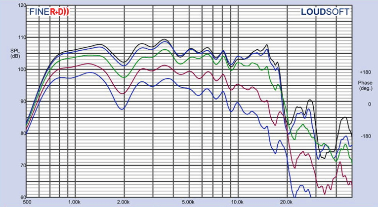
For the next set of SPL measurements, I free-air mounted the Beyma CD-11Nd/TS-194 combination without an enclosure and measured both the horizontal on- and off-axis at 2.0V/0.5m (normalized to 2.83V/1m) from 0° on-axis to 60° off-axis using the LoudSoft FINE R+D analyzer and GRAS 46BE microphone (supplied courtesy of LoudSoft and GRAS Sound & Vibration).
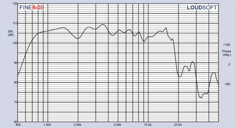
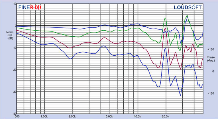
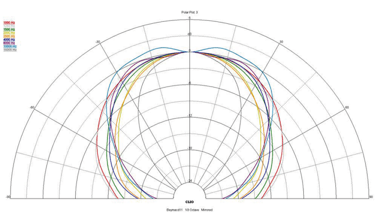
Figure 2 displays the on-axis frequency response of the compression driver/horn, which is relatively smooth ±3dB with no major anomalies from the 1500Hz recommended crossover frequency to about 18kHz, where it begins its second-order low-pass roll-off. Figure 3 shows the 0° to 60° on- and off-axis response in the horizontal plane. Figure 4 displays the normalized horizontal plane response. Figure 5 shows the 180° horizontal polar plot in (in 10° increments with 1/3 octave smoothing applied), generated by the CLIO Pocket analyzer and accompanying microphone (courtesy of Audiomatica).

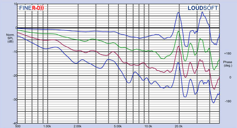
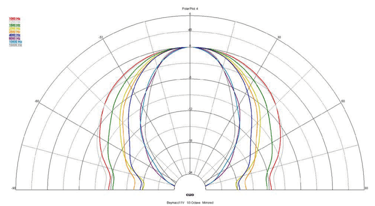
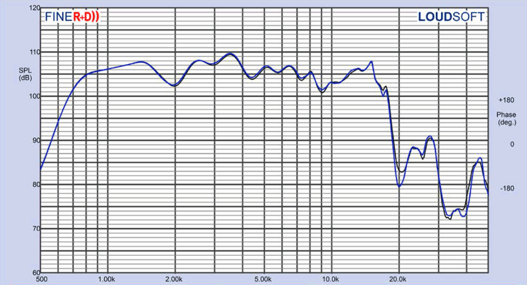
For the vertical plane, Figure 6 depicts the 0° to 60° on- and off-axis response with the normalized version shown in Figure 7. Figure 8 shows the CLIO-generated 180° vertical polar plot (also measured in 10° increments with 1/3 octave smoothing applied). Last, Figure 9 illustrates the two-sample SPL comparison showing the two Beyma CD-11Nd/TD-194 compression driver samples to be closely matched within 1dB or less above the recommended crossover throughout the operating range of the driver.
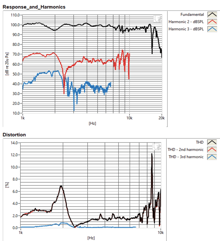
For the remaining series of tests, I again set up the Listen, Inc. AudioConnect analyzer and 1/4” SCM microphone (provided by Listen, Inc.) to measure distortion and generate time-frequency plots. For the distortion measurement, I again mounted the Beyma CD-11Nd/TD-194 combination in free-air and set the SPL to 104dB at 1m (1.98V determined by using a pink noise stimulus generator and internal SLM in the SoundCheck 18 software). I measured the distortion with the Listen microphone placed 10cm from the mouth of the horn. This produced the distortion curves shown in Figure 10.
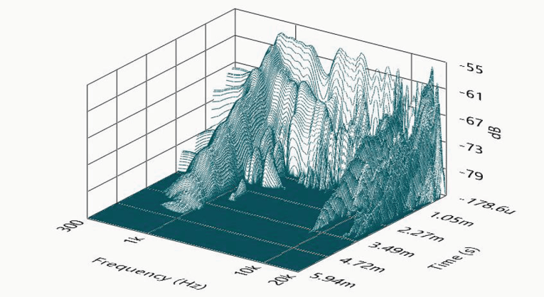
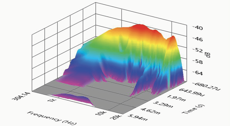
Following this test sequence, I set up SoundCheck 18 to generate a 2.83V/1m impulse response curve for the CD-11Nd/TS-194 combination and imported the data into Listen’s SoundMap Time/Frequency software. Figure 11 shows the resulting CSD waterfall plot. Figure 12 shows the Short Time Fourier Transform (STFT) plot.
Looking over all the measured objective information, I found that the Acustica Beyma CD-11Nd compression driver shows all the attributes of a well-engineered 1” compression driver, exhibiting good performance, nice build quality, and, of course, the use of a proprietary PM4 diaphragm! For more information, visit www.Beyma.com. VC
This article was published in Voice Coil, April 2021.


