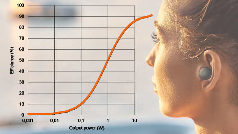
Class-D amplifiers often quote efficiency of 95% or higher at maximum output. Even at 10W out, a nominal 40W amplifier may reach >90% efficiency. But wait – we listen to music at an average output of just a few Watts, if that. And efficiency at those levels is much, much less, often dropping to 20% or lower, as shown in Figure 1 [1]. How can we improve that?
Figure 2 shows the canonical traditional Class-D topology. The audio signal is modulating the duty cycle of the gate drive signals, and the output L-C filter recovers the audio signal, which appears across the capacitor and is sent to the speaker. For efficiency, the switching losses in M1 and M2 as well as the losses in the filter components, in particular the inductor, are important. That inductor is physically a large component (depending on the oscillation frequency) as it should remain linear even when carrying large output currents. It’s relatively bulky, lossy and costly.
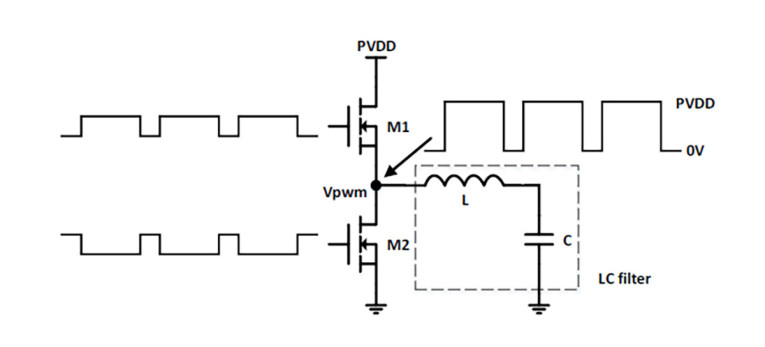
Switching losses predominantly appear in the output devices M1 and M2. Switching speeds cannot be infinite as the internal parasitic capacitances in the devices need to be charged and discharged in each switching cycle, which needs time, however short. There is also the need for what is called a “dead time” where neither device is on, to avoid what would amount to a direct short from the power rail to ground if both would be on at the same time. Switching losses are the product of voltage and current during the switching time when the current change through the device takes a finite time while the voltage across the device changes from full PVdd to zero, which also takes a finite time.
To minimize switching losses, designers strive for minimal dead time and fast switching, but fast switching conflicts with the need to meet EMC requirements. As always in design, it becomes a balancing act.
Thus, even with very low output levels, or with no output (“idle” operation) there is a small dissipation. In modern high-power amplifiers, this is often down to a few Watts, but if the output is similarly low, efficiency has dropped to 50% or less, a far cry from the boasted figures of 95% or more at maximum output. And we know that nobody listens to their music at maximum continuous output, so that 95% efficiency is not really a meaningful number. In fact, Class-D amplifiers can get away with quite small heatsink requirements because the average output power is low and in practice, dissipation is only a little more than the idle dissipation. A nice case of having your cake and eating it too: specify the efficiency for full power and specify the heatsink for low average power.
You may say that low efficiency at low output levels should not be a big problem – the dissipation is still low enough that the amplifier doesn’t need a costly heatsink and enclosure. But for small portable devices such as earbuds or smartphones, dissipation in a small package still must be kept under control. It’s all in the numbers: a 1W Class-D amp for a mobile, battery-powered audio design may have to deliver 10mW of average output, and while at 1W its efficiency may be 95%, at 10mW it is much lower, maybe just 30%. That means that the limited battery power is squandered in heating. But we all want longer playing time for our portable gadgets. Therefore, increasing efficiency in Class-D at low levels gets more attention these days.
In this article I will discuss two approaches, Infineon’s Multilevel Class-D and Silicon Intervention’s Fractal Class-D.
Multilevel Class-D
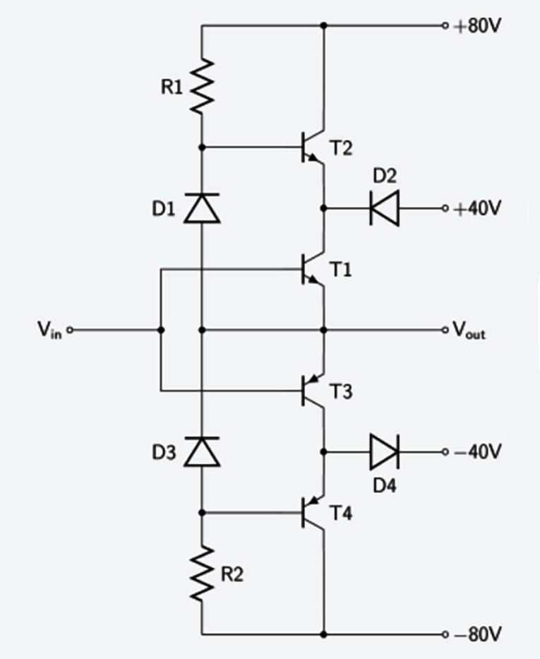
Looking back to Figure 2, an obvious possibility to reduce switching losses at low output levels is reducing the supply voltage during periods of low-level output. Since switch losses are proportional to the square of the supply voltage, this can be very effective. One option is to dynamically change supply voltage “on the fly” depending on the required output level. You may remember that in the heydays of very high-power linear amplifiers, a similar idea was implemented in so called Class-G or Class-H amplifiers (Figure 3). Here, several power supplies were stacked on each other, with a clever arrangement of diode or transistor switching to connect the lowest supply voltage that would support the output voltage to the amplifier [2].
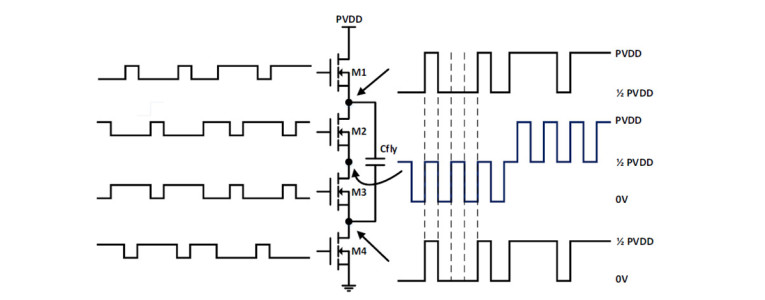
This technology is attractive for Class-D as well; the same fast low-loss switching used for the amplifier can also be used to switch in different levels of supply voltage, and that is precisely what Infineon proposes in its MERUS range of products [3]. Figure 4 shows the basic topology, and the Class-G similarity is immediately apparent. The capacitor Cfly is called a “flying capacitor” and functions essentially as an extra supply rail. In this way, each half-bridge power stage can provide a three-level output signal at the output.
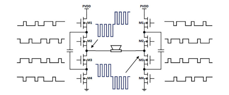
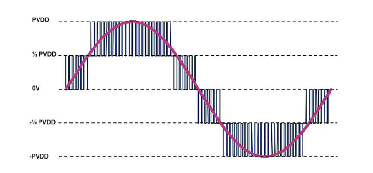
Extending this topology to a full bridge-tied load (BTL) configuration leads to Figure 5. Here, two three-level half-bridges from Figure 4 are combined with a switching pattern in which each half-bridge is modulated with a 90° phase shift relative to the other. The resulting power stage can provide up to five levels of multilevel modulation patterns to a differentially connected speaker load as shown in Figure 6.
This five-level system inherently quadruples the switching frequency at the output nodes of the differentially connected speaker load. Infineon claims much less out-of-band switching residuals, and that - with higher efficiency and better EMI and EMC management - the amplifier can effectively be configured for filter-less operation making it smaller and lower cost. These cost savings are (partially) offset by the need for more power switches in the modulated power supply.
Fractal Class-D
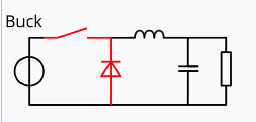
Another topology toward a modulated power supply voltage is the use of the ubiquitous buck regulator [4]. Buck regulators are the usual way to step down supply voltages with low losses as shown in Figure 7. Basically, it is a switch that alternatively connects and disconnects a fixed power source to a low pass L-C filter with a freewheeling diode, providing a voltage to the load controlled by the switch duty cycle. There usually is a feedback loop to control the output voltage within tight limits.
In very demanding (audio) applications with limited current draw, this topology can be followed by a low drop-out linear regulator. In this manner, you can step down a high voltage to a lower one with very small losses and very clean final output. In such applications, the L-C parts and switching times are dimensioned to obtain a smooth, stable, and low ripple output voltage. Clearly, when we want to use the topology to vary the supply voltage for a Class-D amp, the circuit characteristics need to be quite different as the output voltage must dynamically track the audio signal.
Two complications must be considered with this topology however: first, a means to “predict” the audio envelope to make sure the momentarily available output voltage from the buck regulator supports the required audio output voltage. Second, for low distortion, the duty cycles for the Class-D switches must dynamically track the momentary output voltage of the buck regulator. (Which would anyway need to be done in a “regular” Class-D stage where the momentary Vcc supply voltage should be taken into account for each switching cycle).
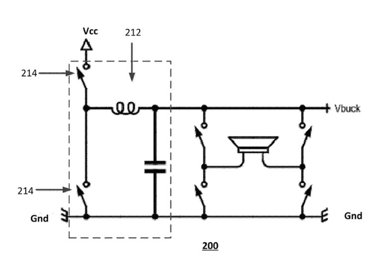
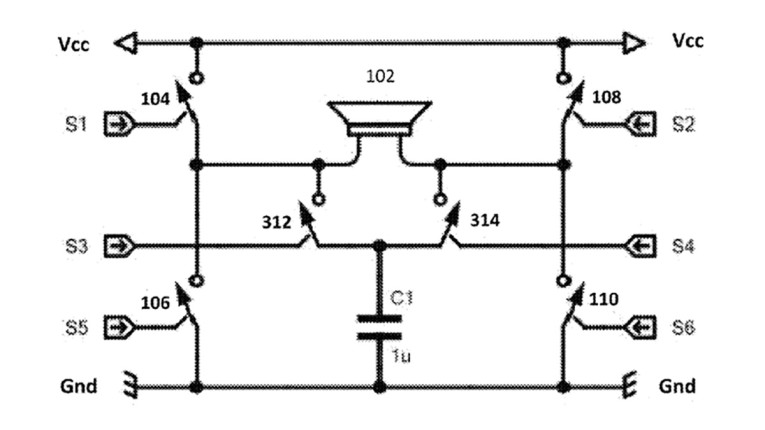
The astute reader will have noticed the similarity between such a buck regulator (Figure 8) and a Class-D output stage - both modulate the output voltage into an L-C output filter – and so did the folks at Silicon Intervention. Their solution is to integrate the buck regulator with the Class-D power stage as shown in Figure 9.
This is based on the fact that the audio transducer is inductive, so it can do double duty as the L in the buck converter circuit. In Figure 9, switches 104, 106, 108 and 110 form the well-known H-bridge of the usual Class-D differential output stage. Additional switches 312 and 314 implement the buck functions together with the inductance of transducer 102 and capacitor C1. As can be appreciated, the switch control sequences and state diagram for such a solution is more complex than for a regular Class-D topology, and interested readers are invited to review the patent [5].
In this topology, christened “Fractal Class-D,” there is no need for an envelope detector to obtain the dynamic audio envelope as would be required with conventional multilevel Class-D, or indeed in any topology that seeks to make the supply voltage track the signal envelope. Such trackers also need a short period to “wait and see” until the audio level drops, before throttling back the supply voltage, and during the wait period, efficiency is lower.
Silicon Intervention claims that the total system efficiency is higher than would be with a separate buck converter of Figure 8, even if that buck converter would be 100% efficient. The company is now licensing the Fractal-D intellectual property, offering expert services for mapping into CMOS process nodes of choice, as well as providing design support for SoC integration in earbuds.
Summary
Driven by the need to be green and efficient, and especially to maximize battery life/playtime in portable gadgets, Class-D efficiency at low output levels is receiving increased attention (an area of focus also for Axign, which audioXpress has been following closely).
Two topologies have been discussed; both increase low-level efficiency and can also have other benefits such as reduced EMI and/or operation without needing output filters. Other technologies such as Neutral Point Clamping are also being explored for the same reasons. aX

References
[1] MERUS multilevel Class-D audio amplifier supports ultra-compact and low-power applications - https://audioxpress.com/files/attachment/2775
[2] “Classes G and H,” Wikipedia, https://en.wikipedia.org/wiki/Power_amplifier_classes#Classes_G_and_H
[3] “Multilevel Class-D,” US 8,558,617 B2, Maxim Integrated Products, Inc., October 15, 2013 - https://patents.google.com/patent/US8558617B2
[4] “Buck Converter,” Wikipedia, https://en.wikipedia.org/wiki/Buck_converter
[5] “Combined Class-D amplifier and Buck regulator,” US 12,021,491 B2, A. Martin Mallison/Silicon Intervention, Inc., June 25, 2024 -https://patents.google.com/patent/US12021491B2
This article was originally published in The Audio Voice newsletter, (#476), July 18, 2024.