Shannon Becker: Tell us a little about your background and where you live.
Ron Tipton: I was born in Chicago, IL, and by the age of eight, I was spending many Saturdays haunting the exhibits at the Museum of Science and Industry with friends. I suppose that was an indication of where my main interests lay. We moved to Kansas City, MO, when I was 10, and I had to content myself with scientific books and magazines: no science museums. I moved to Las Cruces, NM, in 1956 to attend what was then the New Mexico College of Agriculture and Mechanic Arts as a junior in the Electrical Engineering department. (The college became New Mexico State University in 1960.) I did pick up a couple of EE degrees, but I didn’t complete my doctorate because of business. I started Testronic Development Laboratory (TDL) in 1957. Except for a few years in northwest Arkansas (more about that later) and back in Kansas City for a while, I’ve lived in the Las Cruces area since 1956.
Shannon: Tell us about your career as an electrical engineer and your job at White Sands Missile Range.
Ron: In the early 1960s, the telemetry (radio transmission of data from an air- or space-borne vehicle back to the ground) band was around 220 MHz. There were a number of reasons, including smaller antennas, to move the band to 2,200 MHz. I was part of the project to accomplish this move. These were the days of vacuum tubes, so designing and building a transmitter was a big challenge because any vibration in the missile (there was a lot of it) vibrated the tube grids causing frequency modulation of the output, which had to be very low to be acceptable. Several contractors tried and failed but one, Microdot, was successful. It was a big day when we flight tested the transmitter on a missile and it worked fine. Now, of course, the transmitters and receivers are all solid-state and reliable operation is taken for granted.
Most of my other work was with various passive tracking systems. Unlike radar, which is an active tracking system, passive systems use the emissions from the vehicle, usually the telemetry transmitter, to perform the tracking. This usually requires a ground-based antenna field, because they are phase and phase-difference measuring systems, so they benefited from the smaller antennas at 2,200 MHz. By knowing the antenna spacing and the telemetry transmitter carrier frequency, data was collected that was later converted to a track by computer analysis. I retired in 1995, so with the increases in computer performance real-time tracking is probably used today.
The telemetry transmitter’s carrier had to be very stable for this to work. The various detection oscillators in the ground-based receiver were set so the output to the tracking system was usually 5 kHz. The usual phase detectors were period counters. The track data 5 kHz started a high-frequency counter and the reference 5 kHz stopped it so there was some ambiguity in the count. I designed and built a very precise 5-kHz autocorrelation phasemeter using a Motorola DSP56156 digital signal processor. This resulted in 1,700 samples per cycle with a phase measurement resolution of 0.212° with a corresponding lower tracking error. I have never followed up on it, but this technique could be used to design a very precise audio phasemeter.
Shannon: How did you become interested in audio electronics?
Ron: I think it was a result of my love for music. In the early 1950s, I bought an inexpensive 33-1/3/45-rpm turntable, and I needed a preamplifier and power amp to use it. I decided to build them so I found a combination preamp, low-power amplifier in some book. I bought all the parts from Burstein-Applebee in Kansas City, built it, and it worked fine. It used vacuum tubes, of course. I was hooked.
Shannon: Can you tell us about your work with active filters and pseudo-random noise generators? Do the models you used then still function today?
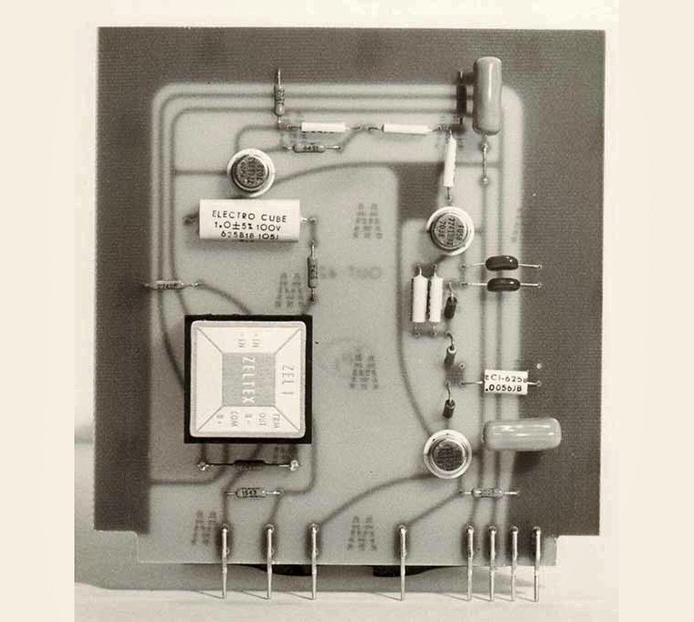
Ron: By the mid 1960s, useful op-amps were available—in particular the LM741 general purpose, the LM301A for better performance, and the higher frequency NE531. It was practical to design and build active filters using either the voltage follower or multi negative feedback topology. I built them in potted modules and as plug-in cards. I had several orders for sets of third-octave bandfilter cards that exactly fit a Hewlett-Packard audio spectrum analyzer. I sold them for less than the HP price! I still have a few of the potted module filters and they work just as they did 50 years ago.
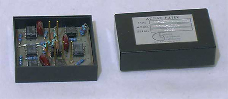
The left-hand unpotted module is a tunable low-pass filter mentioned in the next question as part of the GMS piano tuning aid. It is 2” square to give you an idea of its size. The six gold-plated brass terminal pins extend about 0.2” out of the epoxy potting material to make the electrical connections to the circuit.
The first pseudo-random (P-R) noise generator I designed and built, the model 105, used RTL logic. This was an early logic family in standard DIP packages. I didn’t sell even one of them but it was an interesting learning experience! Next came the model 108, which used 7800 series TTL logic. The 108 and its variants (i.e., the 108-M4, 108-M5, 109, and 111) all sold fairly well.
Perhaps I should mention that P-R noise is just random noise within each sequence but the sequences exactly repeat with the sequence length dependent on the shift-register length and the clock frequency. Thus, we have a random signal with a known period just like a sine or square wave. My article: “Audio Testing With Noise,” Voice Coil, December 2010, discusses P-R noise details.
The 108-M4 and 108-M5 were both “gated” generators. They could put out a noise burst with the duration and repetition rate set on the front panel or triggered by a pulse from a remote location. These were both custom models designed to meet the customer’s needs. This was economical for the customer because the 108-series all used the same size plug-in circuit cards with each card performing a certain function: clock generation, shift-register, gate generator, and so forth. The cards could be “mixed” to provide the required performance. You can find more on this topic, including photos, in the Voice Coil article mentioned earlier.
Shannon: What kind of audio products did you build for GMS? Can you share some of the challenges involved with the designs?
Ron: I designed two lines of guitar amplifiers for GMS and both were marketed by Gretsch. The lower-cost line was the Broadkasters about which I don’t remember much or have any documentation. The premium line was the Nashville series, which included the Pro-Lead, Pro-Steel, and the Pro-Keyboard models. These were rather straight-forward designs with a few exceptions.
The reverb units were mechanical springs in a metal housing with a small loudspeaker without a cone driver at one end and an inductive pickup coil at the other end. I needed some power to drive it because there was quite a bit of loss in the spring, which was about 10” in length. I designed a small power amplifier in a potted module with an aluminum baseplate to transfer the heat to the amplifier’s chassis.
The Pro-Lead model had a tremolo circuit, which was also built as a potted module because Gretsch wanted to keep the circuit under wraps. It had rate and intensity controls on the front panel, a foot-switch jack to turn it on and off, and an LED that illuminated when it was on. I thought it was a rather clever design at the time. Details can also be found on my website.
The Pro-Keyboard had what we called an Accent module which was controlled by a three-pedal footswitch which enabled the musician to instantly change the volume. I though this design was rather innovative because I used the three pedals to get five levels of volume change by sensing how deeply the pedal was depressed. This circuit was also built as a module to hide the design. It used a 4066 analog switch to change the gain of an LM301A op-amp. The other logic chips just decoded the foot pedal positions to control the 4066. The circuit diagram for this design can also be found on my website.
In addition to the guitar amps, I designed a digital piano-tuning aid for the Baldwin grand piano manufacturing plant in Conway, AR. It was a box that produced the 88 piano notes through a built-in 6” speaker. The note to be played was selected by a row of 12-note push buttons and a row of eight octave push buttons or by a two-pedal foot switch, one pedal for the octave and the other for the note. There was also a front panel rotary switch for the normal equally tempered scale, a quarter semitone high or a half semitone high. (Pianos were often tuned slightly high so the structure could settle into the proper tuning.)
The heart of the piano-tuning aid was a 4059 programmable frequency divider, also called a divide by N divider where N was an integer number and the output frequency was the clock frequency divided by N. The integer numbers, N, were read from a PROM. The 4059 output was a square wave which contained too many harmonics to be useful in tuning a piano. (The person doing the tuning matched the output of the piano-tuning aid to the piano note by tightening or loosening the tuning pin.) So I needed to low-pass filter the output. I did this with a frequency-to-voltage converter whose DC output voltage controlled the cut-off frequency of a voltage tunable low-pass filter. The output was a sine wave because the filter’s cut-off frequency tracked the output frequency. I considered this one of my more interesting designs! (The F to V converter and the tunable low-pass filter were potted modules to conserve space and all of the logic chips used were RCA 4000-series CMOS because RCA was a major supplier to the Baldwin Piano and Organ at that time.)
Shannon: You have been TDL’s founder and principal designer for many years. What has been your best experience?
Ron: I think the most interesting task was designing the “Hot Strings” guitar for Chet Atkins. (It was marketed by Gretsch as the “Chet Atkins Super Axe.”) This project is fully described in my article: “Designing the ‘Hot Strings’ Guitar for Chet Atkins” (Multi Media Manufacturer, May/June 2006). But I’ll recount some of the highlights.
Chet heard about my modules in the piano-tuning aid so he came to the GMS plant in the fall of 1975 to discuss the idea of putting some effects modules inside the guitar body. We finally settled on a compressor (2” × 2” × 0.5”) and a phaser (2” × 3” × 0.5”). By the end of August 1976, I had an assembled guitar ready for trial. Chet came to Prairie Grove about mid-September to give it a try. He was generally pleased with the performance, but he wanted a couple of changes. This was also the time he picked the “Hot Strings” name. We made the changes and my final set of drawings is dated January 19, 1977. I’ve never seen a production Super Axe, but I do have several photos.
The rear cover of RCA Records LP APL1-2786 (1978), “Chet Atkins and Les Paul: Guitar Monsters” shows 12 photos of Chet and Les. This guitar can be clearly seen in five of them.
Through the years, I’ve heard from several owners of a Super Axe and replacement modules are now available from the TDL website.
Shannon: What was your first personal project? Why did you build it? Is it still in use?
Ron: My first personal project was the mono phono preamp/power amp I mentioned previously. No, it’s not in use, and I have no idea what happened to it.
Shannon: You wrote an article, “A Vintage Turntable Revisited,” in audioXpress, September 2012. Why did you think it was important to revisit it?
Ron: The revisit was important because of the carbon fiber tube tone arm which let me lengthen it and thus, reduce the tracking error. While it is true that this resulted in a rather large turntable, I think it was worth it. It is still much in use because it sounds very nice.
Shannon: Can you share the details on some other personal audio projects?
Ron: I usually have quite a few projects going at the same time, but I’ll talk about two of them that may be of interest.
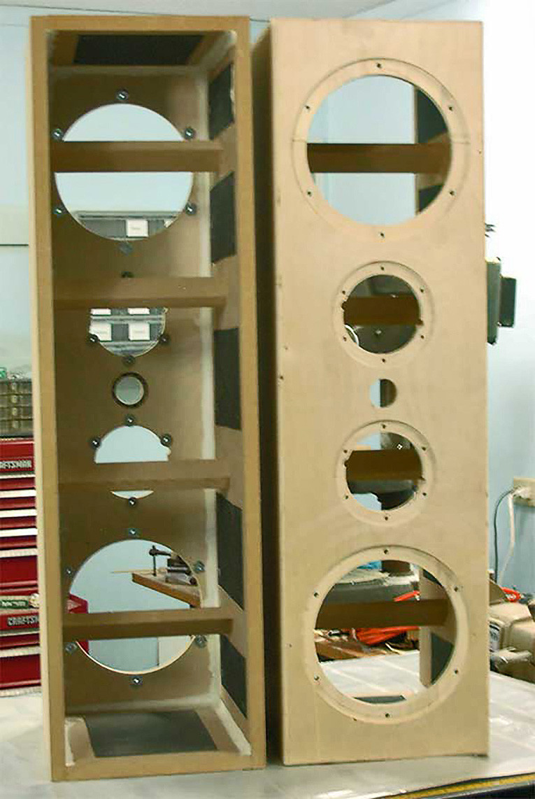
I’m building a stereo pair of three-way speakers, that is, three inputs: base, mid-range and upper frequencies (see Photo 4). These will be sealed enclosures and you can see the internal bracing in the photo. The front and rear panels are 13-ply Baltic birch with 0.75” MDF for the sides, top, bottom, and braces. The box was computer designed for all Dayton (Parts Express) drivers. The top and bottom “holes” are for the 8” reference-shielded woofers (295-366), the next two holes toward the center are for the 2” dome midrange (285-020), and the center hole is for the 0.75” neodymium dome tweeter (275-035). The tweeter is rear-mount, but I have solved that construction problem! The seams are caulked, the black patches on the inside walls are barium-filled vinyl for sound absorption, and the woofer and midrange drivers have T-nuts installed for their mounting screws.
I have built active crossovers, each with the required three outputs, but a Behringer DCX2496 can also be used. The performance comparison will be interesting. Yes, it does require six power amplifiers, but that’s not such a big deal these days even though it would be best if they were all the same type. The simulated overall frequency response looks good.
Some of my projects are studies and they are difficult to describe or to photograph until finished. It’s also difficult to photograph a construction project for which I have all the material, but I haven’t started putting it together yet. So I’ll just tell you what it’s about.
As some of you may know, my company, TDL Technology builds audio equipment for sale. We do a 100-hour burn-in for quality control so our failure rate is nearly zero. But I’ve wondered about doing more. What about bad solder joints or microphonic parts (rare, but possible even with solid-state parts)? It occurred to me that a vibration test might be useful but commercial shake tables are out of my budget. So, what about building one?
The top surface to which the device under test will be fastened is a piece of 20” × 12” × 0.5” thick piece of ceramic tile cemented to a 20” × 12” sheet of 0.75” 13-ply Baltic birch plywood. On the underside of the plywood, two Aura Pro Bass Shakers (Parts Express 299-028) are mounted and wired in series. This composite platform will be supported above its heavy base at its four corners by 0.25” diameter rods and neoprene vibration isolators (McMaster-Carr 94955K31). The device under test will be attached to the top surface with cotton webbing belts fitted with ladder-lock buckles. Accelerometers (Measurement Specialties ACH-01) will be cemented to the top surface and mechanically attached to the device under test to monitor the vibration level.
The Shakers have a frequency response of 20 to 80 Hz so a low-pass filter will be used at the output of the noise generator. I expect white or pink noise will be the most useful. It’s possible that it would also be a useful subwoofer!
Shannon: You have done a lot of work with audio restoration. Why do you think it is important?
Ron: Personal (home) restoration is important because it’s fun and because the music needs to be saved. Record companies have released a tremendous number of records in the past 100-plus years and a few have been remastered and rereleased—a very few. Record archives do their best at restoration but many collections are very large and funds are always limited. I think it’s up to amateur restorers to do as much as possible.
Shannon: We went from vinyl to cassette to CD to DVD to music servers. What do you think the next audio format will be?
Ron: I hope the next big breakthrough will be holographic recording—but we’ll have to wait and see.
Shannon: What do you see as some of the greatest audio innovations of your time?
Ron: The invention of solid-state electronics is at the top of the list. It changed our world. And, I don’t mean just the transistor. LEDs and solid-state lasers made possible so many innovative audio products.
Shannon: Do you have any advice for audioXpress readers who are thinking of building their own sound systems?
Ron: I’ve been building most of my own audio equipment for more than 60 years so it’s possible that I’m prejudiced. As I sit here writing this I can see 10 different power amps and three different phono preamps that I’ve built. Getting into building your own can be addictive so beware! But if you have the inclination and the means, go for it! You will also learn a lot in the process, not only about audio techniques but also how to properly do the construction.
This article was originally published in audioXpress, January 2013.

Ron Tipton (1936 – 2018)