Bass-Reflex Speaker Cabinet Having a Recessed Port
Patent Number: 9,635,454
Inventors: Matthias Larrieu (Ledeuix, France)
Assignee: NEXO (Plailly, France)
Filed: August 6, 2013
Current CPC Class: H04R 1/28 (20060101)
Granted: April 25, 2017
Number of Claims: 27
Number of Drawings: 16
Abstract from Patent
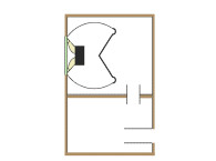
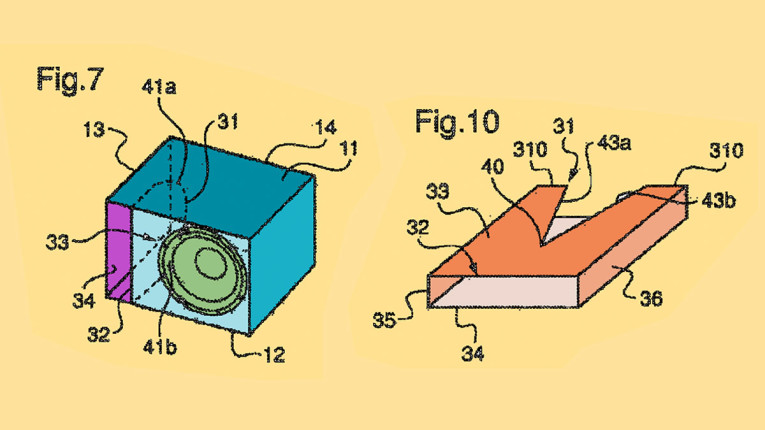
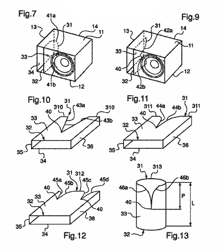
The speaker cabinet (1) includes at least one loudspeaker (2) and at least one port (3), the port having an outlet (32) formed in a wall of the cabinet (1), an inlet (31) inside the cabinet (1), and a casing connecting the inlet (32) and the outlet (31) together, the inlet (32) of the port (3) further having at least one recess in the casing.
Independent Claims
1. A speaker cabinet (1) comprising: at least one loudspeaker (2); and at least one port (3), the port (3) having an outlet (32) formed in one wall of the cabinet (1), an inlet (31) inside the cabinet (1), and a casing linking the inlet (31) and the outlet (32), wherein the port (3) includes at least one recess formed in the casing at the inlet (31) of the port (3), the at least one recess in the port being configured to limit peaks in the response of the port linked to the resonance frequencies (fr), the recess having two edges, a depth p, and a width defined by a distance between the two edges in a direction orthogonal to the depth p, the width of the recess being variable according to the depth p, the width being maximum at the inlet (31) of the port (3) defining an initial width of the recess, wherein the casing of the at least one port (3) is located within the speaker cabinet at a location spaced apart from the at least one loudspeaker (2).
8. A speaker cabinet (1) comprising: at least one loudspeaker (2); and at least one port (3), the port (3) having an outlet (32) formed in one wall of the cabinet (1), an inlet (31) inside the cabinet (1), and a casing linking the inlet (31) and the outlet (32), wherein the port (3) includes at least one recess formed in the casing at the inlet (31) of the port (3), the at least one recess in the port being configured to limit peaks in the response of the port linked to the resonance frequencies (fr), the recess having two edges, a depth p, and a width defined by a distance between the two edges in a direction orthogonal to the depth p, the width of the recess being variable according to the depth p, the width being maximum at the inlet (31) of the port (3) defining an initial width of the recess, wherein the casing of the at least one port (3) is located within the speaker cabinet at a location spaced apart from the at least one loudspeaker (2), wherein the at least one recess is formed on a flat partition of the casing of the port.
21. A speaker cabinet (1) comprising at least one loudspeaker (2) and at least one port (3), the port (3) being composed of a casing, formed by at least one partition (33), the casing having an inlet (31) and an outlet (32) and defining an internal volume of the port (3) with the inlet (31) situated in the cabinet (1) and the outlet (32) constituted by an opening formed in one wall of the cabinet (1), and the port comprising a recess extending into the partition (33) from the inlet (31), wherein the at least one recess in the port is configured to limit peaks in the response of the port linked to the resonance frequencies (fr), and wherein the casing of the at least one port (3) is located within the speaker cabinet at a location spaced apart from the at least one loudspeaker (2).
23. A speaker cabinet (1) comprising at least one loudspeaker (2) and at least one port (3), the port (3) being composed of a casing, formed by at least one partition (33), the casing having an inlet (31) and an outlet (32) and defining an internal volume of the port (3) with the inlet (31) situated in the cabinet (1) and the outlet (32) constituted by an opening formed in one wall of the cabinet (1), and the port comprising a recess extending into the partition (33), the recess being formed by two curved edges extending from the inlet (31) and joined at one end (40), the two edges of the recess defining between them a width of the recess which is increasingly narrow according to a non-linear function, giving the recess an arched shape, wherein the at least one recess in the port is configured to limit peaks in the response of the port linked to the resonance frequencies (fr), and wherein the casing of the at least one port (3) is located within the speaker cabinet at a location spaced apart from the at least one loudspeaker (2).
24. A speaker cabinet (1) comprising at least one loudspeaker (2) and at least one port (3), the port (3) being composed of a casing, formed by at least one partition (33), the casing having an inlet (31) and an outlet (32) and defining an internal volume of the port (3) with the inlet (31) situated in the cabinet (1) and the outlet (32) constituted by an opening formed in one wall of the cabinet (1), the port comprising a recess extending into the partition (33), the recess being formed by two edges extending from the inlet (31) and joined at one end (40) in a pointed shape, wherein the at least one recess in the port is configured to limit peaks in the response of the port linked to the resonance frequencies (fr), and wherein the casing of the at least one port (3) is located within the speaker cabinet at a location spaced apart from the at least one loudspeaker (2).
Reviewer Comments
The bass-reflex enclosure system while embodying many advantages in efficiency, enclosure size, bandwidth and transducer displacement requirements, also has a number of troublesome quirks and trade-offs that can negatively impact the system’s acoustic performance. One general category of problems with this type of system relates to undesirable spurious outputs from the system vent (or port, as it will be referred to in this review).
Bass reflex systems incorporate an elongated pipe as a port coupling the internal volume to the external environment, which is used as an acoustic mass coupled to the enclosure volume acoustic compliance to create a fundamental Helmholtz resonance at the lowest usable frequencies of the system (or at other low frequencies within the system bandwidth when applied to multi-tuned or bandpass enclosures). Ideally, the acoustic mass and compliance would interact to create a single Helmholtz resonant frequency and be substantially free of any other spurious outputs. Unfortunately, in most cases the port output is not limited to the pure, single tuning frequency output.
Ports can be a source of several problems, including turbulence and the associated audible “chuffing,” the communication of internal enclosure standing wave resonances to the external environment, and, the subject addressed by the patent of this review, “pipe-resonances.”
Pipes are very efficient at developing a wide band of resonances associated with their fundamental resonance, usually corresponding to the frequency where the length of the pipe is a quarter wavelength (depending on the input to output form factor) with a series of resonances at each odd multiple of a quarter wavelength (1/4, 3/4, 5/4, etc.). For large, high compliance enclosures, the port diameter may be greater than the port length for a given tuning frequency, and, therefore, pipe resonances will not be efficiently created. But, with smaller enclosures, for a given tuning frequency, the port is often quite long, with the length being much more than twice the port diameter, allowing pipe resonances to develop efficiently.
The result in real-world systems is that these pipe resonances will tend to form in the lower midrange frequencies and their outputs can equal or exceed that of the direct output from the loudspeaker transducer, particularly in a full-range or two-way loudspeaker where the driver is radiating at full output into the enclosure throughout the majority of the midrange frequencies. (The problem is somewhat mitigated in subwoofers and multi-way systems where the woofer is low-pass filtered and the sound radiated to the inside of the enclosure is attenuated in the mid-band.)
As this problem is difficult to fix, many loudspeaker designers ignore the problem and are hopeful that masking from the primary system output will adequately hide the audible effects. There have been numerous approaches by others to minimize port-based pipe resonances, with some of the more significant ones falling into three categories (all of these are worthy of study):
- Using a Helmholtz absorbing chamber branched off of the port along its length and tuned to the primary pipe resonance, with Philips and Yamaha doing some of the earliest work in this regard, such as US 5,012,890, “Acoustic Apparatus” by inventor Katsuo Nagi, to Yamaha, and US 5,261,006, “Loudspeaker System Comprising a Helmholtz Resonator Coupled to an Acoustic Tube” by Joris A. M. Nieuwendijk of Philips, applied to bandpass enclosures with long vents. For further study, one can read about this approach in the Audio Engineering Society (AES) paper by J. A. M. Nieuwendijk of Philips, “Band-Pass Loudspeaker with Long Port,” AES 94th Convention, March 1993.
- Perforating the port walls near the halfway point along the length of the port, see US 5,109,422, “Acoustic Apparatus” by inventor Kasunari Furukawa at Yamaha, and US 6,275,597, “Loudspeaker System Having a Bass-Reflex Port” by Nicolaas Roozen of US Philips Corp.
- Using multiple ports of equal acoustic mass and differing lengths to distribute the resonances — see US 5,115,473, “Transducer Having Two Ducts” by Makoto Yamagishi of Sony Corp. This last example is a parallel precursor to the invention currently under review.
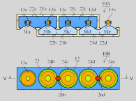
Disclosed in the current invention is a bass reflex system incorporating a singular port with distributed effective length. The port is unique in having the internal entry point into the port distributed along the first portion of the length of the port. This takes numerous forms, but a primary configuration includes at least one slot on the side of the port, starting wide at the internal opening and shaped to a narrow point toward the middle of the port length. For the older folks reading this, the shape is very similar to the opening on the front of the old Karlson enclosures of the 1950s — see US 2,816,619.
The port may include two V-shaped slices at the opening either centered or with one at each side of the port. To some degree, this approach mimics the resonant distribution of the dual port approach by Sony, listed earlier in this review. This approach has also been incorporated by the DIY community into the exit openings of transmission lines and tapped horns.
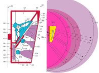
Besides reducing the port resonances relative to minimizing tonal distortions, the inventor has also observed that the amplitude and phase anomalies in the midrange due to port resonances can also impact mid-band directivity, which is illustrated in directivity measurements in the patent document (see the figures shown from US Patent 9,635,454).
This architecture should be effective at distributing and smoothing port resonances as stated, but as with many of these port resonance solutions there are side effects that may or may not be more significant that the original problem.
In the case of this architecture, there are at least two issues of concern. First, with this approach, the acoustic mass is less for a given total length of the port (cabinet depth to accept port length is at a premium in small enclosures), and therefore, the tuning frequency is moved up in frequency or the port must be increased in length (or reduced in cross-sectional area) if the tuning frequency is to be maintained.
Second, it has been found that internal ingress and external egress opening must have substantially the same form if turbulence is to be minimized. This isn’t addressed in the patent, but one can imagine that the external exit of the port could be reconfigured to more closely match the acoustic form of the internal opening to create a more favorable input/output symmetry.
All in all, the invention appears to provide another solution that should be effective at minimizing the primary problem of port pipe resonances while being easy to fabricate and exhibiting manageable side effects. VC
This article was originally published in Voice Coil, August 2017.