Smaller, cheaper, better: time’s arrow for technology flies rapidly and inexorably. And so it is for microphones. Microphones based on Micro-Electronic Mechanical Systems (MEMS) technology are now made in the billions, and totally dominate the huge cellphone, tablet, and pad market. Compared with electret microphones, MEMS mics have a wide operating temperature range, good resistance to the stresses of soldering, and low current requirements. They are also physically small and light and mechanically rugged. The small size has enabled their use in arrays, which is a great aid to DSP noise cancelling in many devices.
MEMS transducers generally are constructed in a similar manner as microchips (i.e., by using a piece of high purity silicon as a base and performing a series of etching and deposition operations). This not only makes the resulting parts far more consistent than usual mechanical assembly, but makes the integration of signal conditioning much simpler.
Most MEMS work on the condenser principle, that is, they have a diaphragm and a back plate with a constant charge, and the acoustic pressures cause the distance between them (and hence the voltage) to be modulated. Until recently, the disadvantages of MEMS have included low dynamic range and uneven frequency response due to the Helmholtz cavity resonance from the front and/or back cavity. The small diaphragm size has also resulted in a significantly higher noise floor. This is likely the reason that electrets have still dominated in lower cost measurement application. In the past few years, though, MEMS technology has improved to the point where it’s a viable option for test and measurement applications.
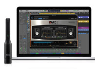
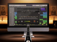
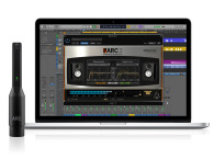
The ARC 2.5 Room Correction System described by Ron Tipton in his review (found here) makes use of a MEMS-based measurement mic, which replaces an electret-based mic used in earlier versions of the system. Ron was kind enough to send me the old mic, which appeared to be configured for diffuse-field measurement. Running it through some basic tests, I quickly determined why IK Multimedia may have wanted to upgrade it—the top octave is severely rolled off (-10 dB at 20 kHz) and the distortion is relatively high. The current MEMS mic is said to have an omnidirectional (free-field) polar pattern.
Microphone Setup
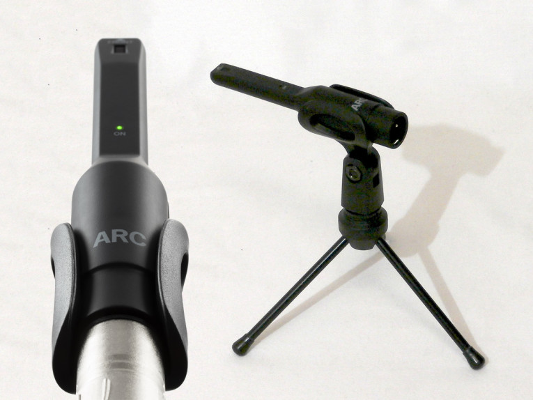
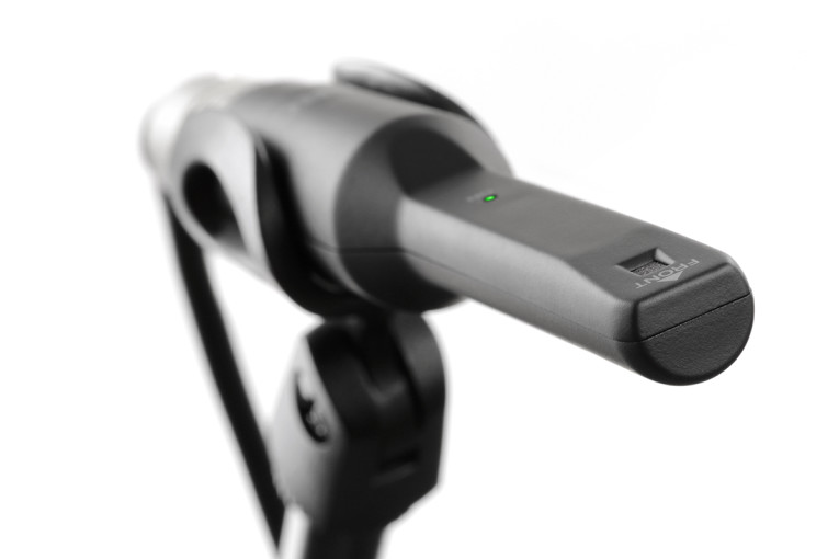
The MEMS mic is packaged in an injection-molded plastic case (see Photo 1), with the mic inlet on the top side when the mic is placed as directed (the tip pointed toward the speaker). The MEMS mic attaches via a standard XLR cable to the input of any microphone preamp that can supply phantom power. There’s a small green LED on the top side as well to indicate when power is present.
With the case removed, the MEMS element can be seen to be mounted on the top side of PCB and is a top-port sensor (see Photo 2). The use of a top-port MEMS and the top side mounting are necessary design elements to get a horizontal polar pattern that is omni-directional. Of course, the trade-off is that the vertical polar pattern will not be omni, which may be an issue for some measurement applications.
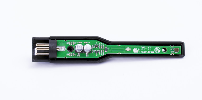
Likewise, with this sort of mounting, the MEMS mic will not give accurate near-field results for woofer measurements. The last point turns out to be moot, as we will soon see.
Although the MEMS element does not have a readable marking on it, it looks similar to the Knowles SPH1642HT5H-1, part of the SiSonic series, and referencing the datasheet for that part (see Resources) gives some insight into the operation of this family of elements (similar parts can be sourced from InvenSense and PUI, among others). The MEMS element includes the sensor itself, a buffer, and an output amplifier. The other parts on the PCB are used to convert phantom power into an operational voltage suitable for the MEMS element and buffering circuitry to drive cables and a mic preamp (see Photo 3).
Measurements
All my measurements were done using an Audio Precision APx515 analyzer and an APx1701 transducer interface. The reference microphone was a calibrated PCB Piezotronics 376A32 0.5” phantom powered prepolarized condenser microphone (the subject of an upcoming review), which comprises a 377B02 capsule and a 426A14 preamplifier.
The performance specifications provided for the IK Multimedia MEMS mic are somewhat rudimentary and no sensitivity is given. I measured it to be 12.4 mV at 94 dB SPL (or -38 dB). The quasi-anechoic on-axis frequency response of the MEMS microphone above 1 kHz is shown in Figure 1, and was obtained by comparison to the reference using a swept tone stimulus played through a Vanatoo Zero powered loudspeaker at a 1.5 m distance — taking the ratio of the two microphones’ responses removes the loudspeaker’s frequency response from the measurement. The impulse response derived from the swept tone was gated to remove room effects and yield the quasi-anechoic measurement.
Many MEMS elements show a peak at 21 to 25 kHz, which is used as a way of extending treble response. In this case, the resonance was at about 23 kHz, and the peaking caused a smooth response rise in the top audible octave, with the 20 kHz response being 6 dB elevated compared to the midrange. The response was otherwise smooth, and this rise was easy to equalize out in software (as IK Multimedia almost certainly did in the ARC 2.5 system). If you plan to use this mic for speaker measurements, you can either electrically equalize out the treble rise with some first-order RC filtering or compensate in your measurement software. If we assume that the MEMS element is the Knowles MEMS or something similar, this should be quite consistent from part to part, so a good approximation for correction is a single pole low-pass filter with a -3 dB point at about 15 kHz.
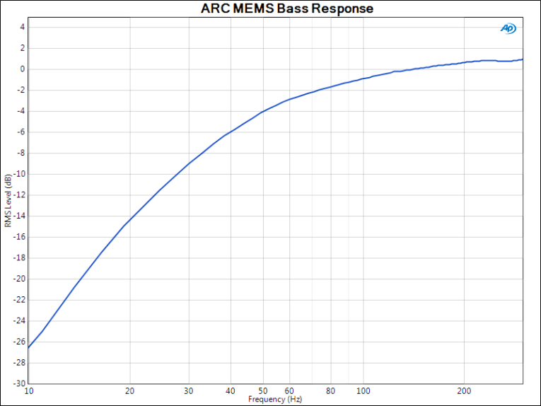
Figure 2 shows the bass response of the IK Multimedia MEMS mic, obtained by measurement of a woofer with both the reference PCB Piezotronics mic and the ARC MEMS, then taking the ratio of the results. From this graph, you can see that the -3 dB point for the MEMS mic is at about 65 Hz, which is high enough to rule out using this microphone for most woofer measurements. As mentioned before, the construction of this mic also prevents it from being used for most near-field woofer measurements.
I measured the IK Multimedia MEMS mic’s self-noise by using the BLANK chamber I have described in previous articles (basically burying the microphone in a tub of sand and kitty litter). With a 20 kHz bandwidth and A-weighting, the noise was 29 dB SPL equivalent. This is 65 dB below the usual 94 dB SPL reference, so the mic exactly meets its 65 dB signal-to-noise ratio (SNR) specification.
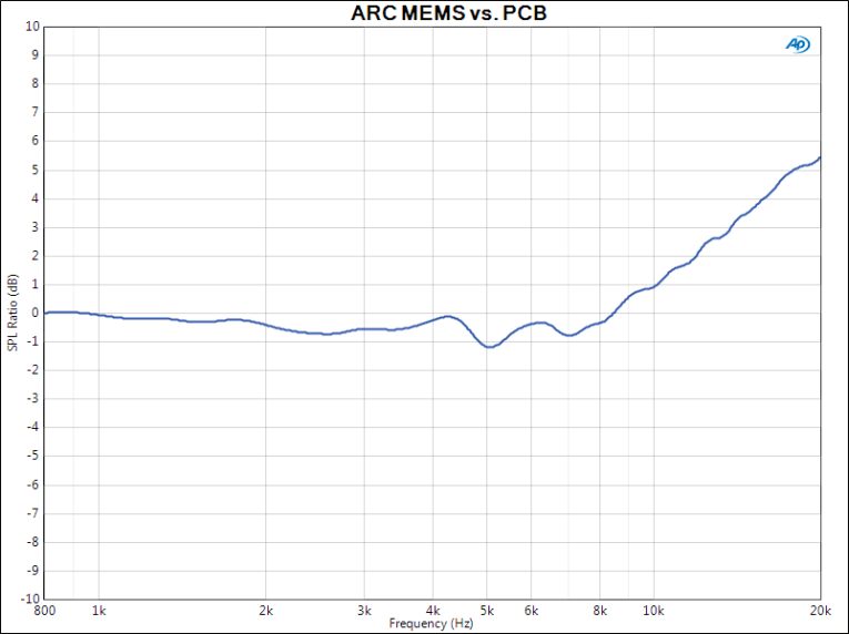
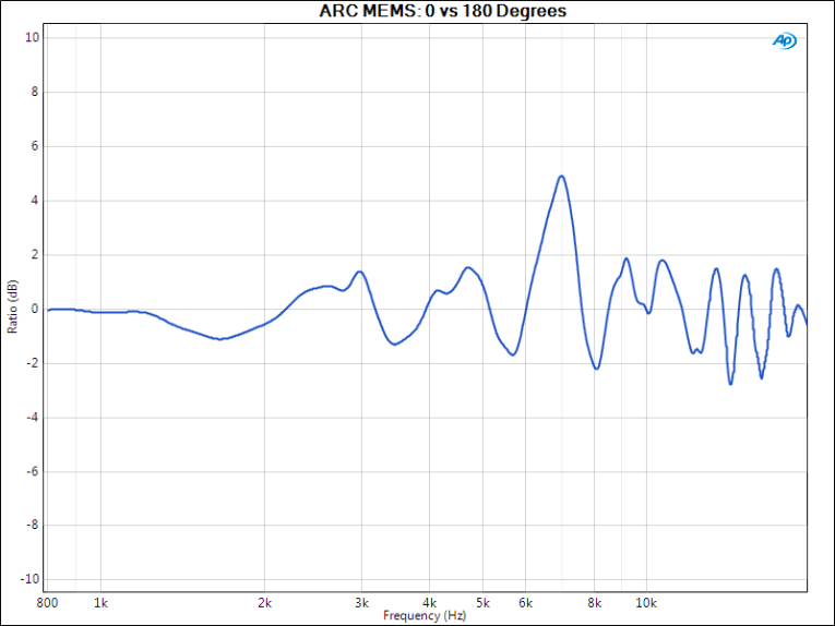
When I started doing polar pattern measurements, I saw some rather complex lobing in the upper midrange and treble. Figure 3 shows why this might be — this graph is the ratio between on-axis and 180° frequency response. For a perfectly omni-directional microphone, this should be a flat line at 0 dB. For real world omnis using traditional technologies (condenser or electret), one usually sees a treble rolloff of several decibels and a few small ripples from diffraction. The IK Multimedia MEMS mic has an effective diaphragm diameter of roughly a millimeter, so the usual treble rolloff is not evident—in that sense, this is the best I’ve ever seen in a mic measurement. Because of the unusual mounting of the element, diffraction effects become more significant, and this graph shows some pretty significant peaks and dips in the upper midrange at 180° (especially at 7 kHz, which may correspond to the distance between the MEMS port and the front of the microphone) that do not appear in on-axis response.
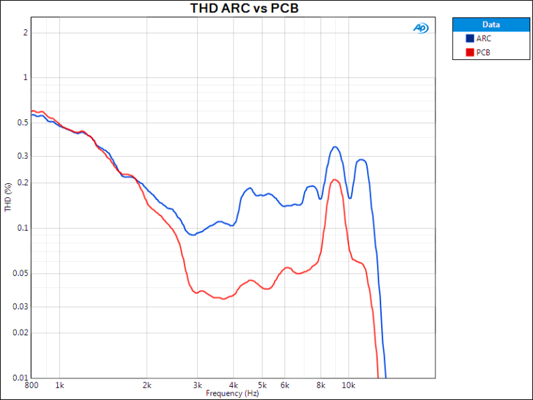
My usual method for measuring microphone distortion is to do a near-field measurement at low frequency on a woofer. The small distance from the woofer means that for high SPL, the excursion (and hence distortion) can be quite low. This method won’t work for the MEMS mic because of the top-ported layout, but in the spirit of improvisation, I did some 1 m on-axis distortion measurements of a loudspeaker system and compared it to the same measurements acquired with the reference PCB Piezotronics 376A32 microphone, which has the lowest distortion of any mic I’ve tested so far. Figure 4 shows the distortion vs. frequency of the loudspeaker at 78 dB SPL measured with both microphones. At low frequencies, the loudspeaker distortion predominates, but at higher frequencies, the distortion drops below the MEMS mic’s distortion floor, which is about 0.1 to 0.2% THD. At the same frequencies, the PCB mic shows about 0.04% distortion, which is likely limited by the loudspeaker, not the microphone. By comparison, the last generation microphone for the ARC 2.0 room correction software showed about 0.5% THD at the same SPL. The new MEMS mic is a significant improvement.
Bringing the MEMS mic in to about 1” away from the woofer cone, the 3% distortion point at 200 Hz was about 119 dB SPL. This is consistent with the Knowles MEMS microphone’s element rating of 124 dB SPL for 10% distortion. Retesting at 1 kHz, the distortion measurement looked about the same, so it is apparently related to diaphragm displacement rather than turbulence in the mic element cavity.
Conclusions
I‘m always fascinated when a new technology crashes the party. The low-cost, solderability, and environmental resistance of MEMS are compelling advantages, and the tiny diaphragm size suggests some interesting potential virtues. For this microphone using the latest generation of MEMS sensors, the disadvantages (noise and frequency response flatness) are demonstrably improved compared to earlier generations. The IK Multimedia MEMS mic works beautifully with its ARC 2.5 system, but the technology still has not quite reached the point where it can be used for general measurement because of the bass rolloff and relatively high distortion. The rear response at the top octave is impressive, though, as is the midrange flatness on axis.
For recording use, the 29 dB noise floor is higher than one might want, at least for use in a studio. For some outdoor or live concert applications, this might be good enough, and the excellent environmental stability and ruggedness of the MEMS sensor may be more important than the noise floor.
Overall, this MEMS microphone is a significant upgrade compared to the mic previously provided with the ARC system, and its virtues (ruggedness and stability) are considerable. The pairing with the ARC 2.5 room correction software made a significant improvement in the sound of my recording monitors. I’m looking forward to seeing what the next generation of MEMS sensors can do to expand the capability of that technology. aX
 Sources
IK Multimedia ARC System 2.5
IK Multimedia | www.ikmultimedia.com/products/arc2
Knowles MEMS microphone element
Knowles | www.knowles.com
About the Author
Stuart Yaniger has been designing and building audio equipment for nearly half a century, and currently works as a technical director for a large industrial company. His professional research interests have spanned theoretical physics, electronics, chemistry, spectroscopy, aerospace, biology, and sensory science. One day, he will figure out what he would like to be when he grows up.
This article was originally published in audioXpress, March 2018