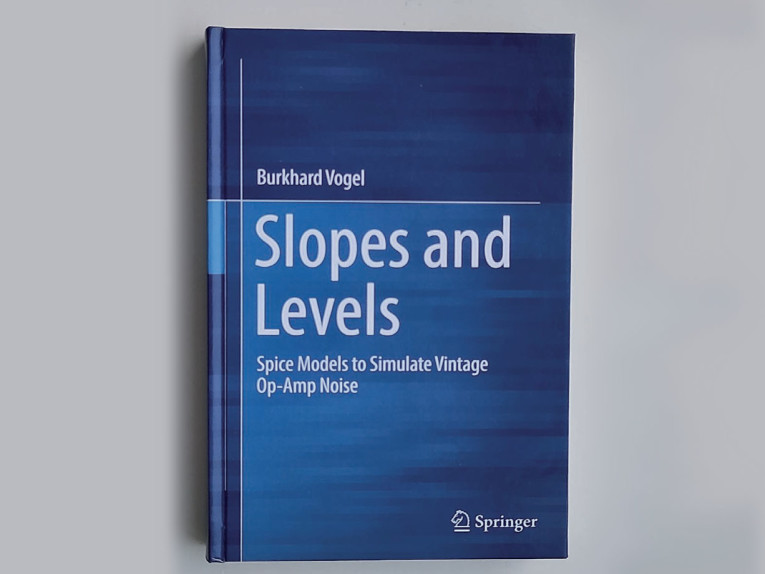
The first question that came to my mind when I read the title of Burkhard Vogel’s book Slopes and Levels: Spice Models to Simulate Vintage Op-Amp Noise was why such a book would be required, given that op-amp manufacturers nowadays publish op-amp macromodels. Vogel answers that question convincingly: Some manufacturer-supplied models are way off. For example, he found a TL071 model featuring a flat equivalent input noise voltage density of 12 nV/√Hz while a real TL071 is closer to 18 nV/√Hz at 1kHz with a substantial increase below 100Hz. Another example is an NE5534A model with almost 6.5 nV/√Hz of white voltage noise, when a real NE5534A typically produces 3.5 nV/√Hz at 1kHz.
Vogel therefore started making his own LTspice op-amp noise models. He describes in detail what methods he used and what sanity checks he did to see if his models gave the expected results. The methods and equations are easy to understand once you get used to his notation, which doesn’t take long, as it is logical and consistent.
The Beginning Chapters
In the first chapters, Vogel tries to use LTspice’s UniversalOpamp2 model, but finds it too limited. The model only supports white noise and flicker noise with a slope of -10 dB/decade, while many noise graphs in datasheets show different slopes. On top of that, the noise currents at the positive and negative inputs are always fully correlated with opposite directions, which also doesn’t match reality. He therefore switches to a UniversalOpamp2 with switched-off noise and augments it with one noise voltage and two noise current sources. By using Laplace expressions and controlled sources, he can make whatever slopes and correlations are required.
Vogel’s approach is strictly a black-box curve-fitting approach. That is unfortunate, because it leads to inaccuracies, some relatively minor ones and one very big one.
For all op-amps, he assumes the current noise to be independent of the voltage noise. This is approximately true for bipolar op-amps and for field-effect transistor (FET) op-amps at low frequencies, but not for FET op-amps in the frequency range where the current noise increases with 20 dB/decade. The low-frequency current noise of FET op-amps is shot noise of junction leakage currents, but the increase at high frequencies is due to the thermal noise in the FET channel in combination with the FET’s gate capacitance. As the thermal noise in the channel also causes the equivalent input noise voltage, they are dependent. Fortunately, this only causes an inaccuracy in the total noise when the source has a very high impedance that is largely or completely reactive, such as a condenser microphone capsule.
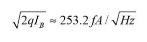
When trying to find a suitable model for the equivalent input noise current density of an NE5532A, Vogel faces the problem that the datasheets only specify the noise current at 30Hz and at 1kHz, which is not enough to solve the slope of the flicker noise, the level of the white noise and the corner frequency. He rather arbitrarily assumes a -20 dB/decade slope to find a solution that passes through the 30Hz and 1kHz data points, but with a non-black-box approach, he might have realized that the equivalent input noise current is predominantly shot noise and flicker noise of the base current of the input differential pair of the NE5532A and that the base current is the input bias current. The typical input bias current of an NE5532A is 200nA, corresponding to white shot noise of:
Vogel on Correlated Current Noise
In my opinion, Vogel is incorrect in Chapter 10, “The Correlation Matter,” about the correlation between the current noise at the positive and at the negative op-amp inputs, and in Chapter 11, which contains the corresponding Mathcad code. He makes the assumption that whatever correlation between the noise currents is found in the manufacturer’s model is the truth, but if the manufacturer’s noise models were reliable, there would be no need for the book in the first place.
The manufacturer’s model of the LT1128 (unity gain stable variant of the LT1028) turns out to have fully correlated input noise currents with opposite directions and a level around 1 pA/√Hz. This contradicts the “Total noise versus unmatched source resistance” graph in the LT1028/LT1128 datasheet, which implies an effective input noise current just above 3 pA/√Hz when the impedances driving the positive and negative inputs are very different. It also contradicts noise current measurements of Paul Horowitz and Winfield Hill, authors of The Art of Electronics, who Vogel quotes in his Figure 14.16. These show about 4 pA/√Hz. What it all boils down to, is that the Linear Technology model only models the differential component of the input noise currents and not the much larger common-mode component.
Following Linear Technology’s inadequate noise model for the LT1128, Vogel makes a model with the same deficiencies and even conjectures that op-amps with base current compensation have fully correlated input noise currents with opposite directions. This would be true if base current compensation circuits sensed the sum of the momentary positive and negative input bias currents and corrected for those, but as far as I know, such base current compensation circuits have not been invented yet. Real base current compensation circuits use one or more transistors that are a (scaled) copy of the input transistors and mirror out its/their base current. As the copies closely match the input transistors, this results in the correct DC compensation current. It doesn’t compensate for the common-mode component of the input noise current, because the scaled copies generate shot noise independently of the input transistors—in some implementations, the common-mode component of the input noise current even gets much larger, meaning that the noise currents of the positive and negative inputs are strongly correlated with equal rather than opposite directions.
Base Current Compensation Example
My Figure 1 shows a simplified schematic of the base current compensation circuit of an LT1028 or LT1128. Several cascodes, helper transistors and a trick to ensure that Q13 and Q14 have the same collector-emitter voltages as Q1 and Q2 have been left out for simplicity, the full circuit can be found in the LT1028/LT1128 datasheet. Transistors Q1 and Q2 are the input differential pair. Q13 and Q14 are the model transistors, which are biased at a six times lower current; these transistors are presumably also six times smaller than the input transistors. The sum of the base currents of Q13 and Q14 is mirrored and amplified by current mirror Q6A-Q6B-Q5. The mirrored and amplified currents are connected to the inputs to compensate for the base currents of the input pair.

First looking at the parts that are not common to both inputs: with their base currents of 4.5μA, the input differential pair transistors each have a base shot noise √2qIB of 1.2 pA/√Hz. Transistors Q6B and Q5 each contribute 1.2 pA/√Hz of collector shot noise. If these were the only noise sources, we could add the squares and take the square root, and end up with uncorrelated input noise currents of 1.7 pA/√Hz at the positive and 1.7 pA/√Hz at the negative input. Mathematically, you can split this into a common-mode noise current of 1.2 pA/√Hz per input and a differential noise current of 1.2 pA/√Hz, which is reasonably close to the specified 1 pA/√Hz differential noise current. So far, so good.
Now looking at the common parts: Q13 and Q14 together have a base current of 1.5µA and together produce 0.693 pA/√Hz of base shot noise. Q12 does almost nothing and Q6A produces another 0.693 pA/√Hz of collector shot noise. Taking the root of the sum of the squares, the total is 0.98 pA/√Hz. The amplifying current mirror amplifies this by three and injects it into the positive input and into the negative input, completely correlated with the same direction. Adding the 1.2 pA/√Hz of common-mode noise current that we already had, the total common-mode noise current becomes 3.177 pA/√Hz.
When one input is driven from a very low impedance and the other from a not so low impedance, which is the normal use case for a low-noise op-amp since you normally keep the feedback network impedance very low, both the common-mode and the differential-mode noise currents come into play and the total noise current is 3.396 pA/√Hz, which is in between the values from the “Total noise versus unmatched source resistance” graph shown in the LT1028/LT1128 datasheet and the Horowitz and Hill data.
A minor mistake in Chapter 20 about the OPA134 is Vogel’s interpretation of the simulation graphs 20.15 and 20.16. These don’t show a weird bug in the noise model, but simply that the manufacturer has included about 4pF of capacitance from each input pin to the supplies in the macromodel.
Overall Impression
While Burkhard Vogel’s Slopes and Levels may not be the last word yet, it is definitely a valuable resource for anyone interested in accurately simulating the noise of op-amp circuits.
Title: Slopes and Levels - Spice Models to Simulate Vintage Op-Amp Noise
Author: Burkhard Vogel
ASIN: B09ZNYCRZ1
ISBN: 978-3-030-99443-3
Publisher: Springer (May 6, 2022)
Pages: 363
 About the Author
When Marcel van de Gevel was 9 years old, he got a Philips electronics kit. He has been an electronics hobbyist ever since, with a particular interest in audio circuitry. He also turned electronics into his profession: in 1993, he got an ingenieur's (MSc) degree (cum laude) in electronics engineering from the Delft University of Technology. Professionally, he mainly works on RF integrated circuits for consumer equipment.
This article was originally published in audioXpress, March 2023