If you aren’t aware of AP’s background, the company was founded by four former Tektronix engineers: Dr. Richard Cabot, Bruce Hofer, Bob Metzler, and Robert Wright. The first product, the computer controlled AP System One, is near legendary for its 0.0005% (-106 dB) background distortion oscillator. Over the years, AP has produced some of the industry’s best computer-controlled hardware analyzers. Today, the company has a lineup of five software controlled hardware analyzers (the APx555, the APx52x, the APx58x, the APx515, and the APx511).
The only thing AP hadn’t produced was a strictly software-based analyzer that uses external sound card technology: Enter the recently released APx500 Flex Audio Analyzer designed to work with third-party USB audio recording interfaces.
After announcing the launch of the APx500 Flex in the December 2019 issue of Voice Coil magazine, I contacted my friends at AP, and arranged for Dan Knighten (AP’s VP of Product Development) and Michael Martin (AP’s Product Marketing Manager) to bring a complete APx 500 Flex analyzer to my office and assist me in performing a series of R&D type measurements on the driver featured in my Test bench column (which audioXpress will make available online as well).
The APx500 Flex
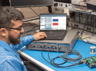
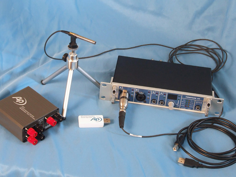
Photo 1 shows the equipment used with the APx500 Flex software. This included the RME Fireface UC, a multichannel 24-bit, 192 kHz high-speed audio interface, the AP 13M23 1/4” measurement microphone (developed by PCB Piezotronics for AP), the AP IMP1 impedance test fixture, and the APx500 Flex key (hardware lock). Once Knighten loaded the software on my laptop dedicated to various analyzers (LoudSoft FINE R+D, Listen SoundCheck, Clio Pocket, and the Dayton Audio OmniMic V2), the process was fast and relatively easy.
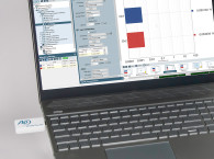
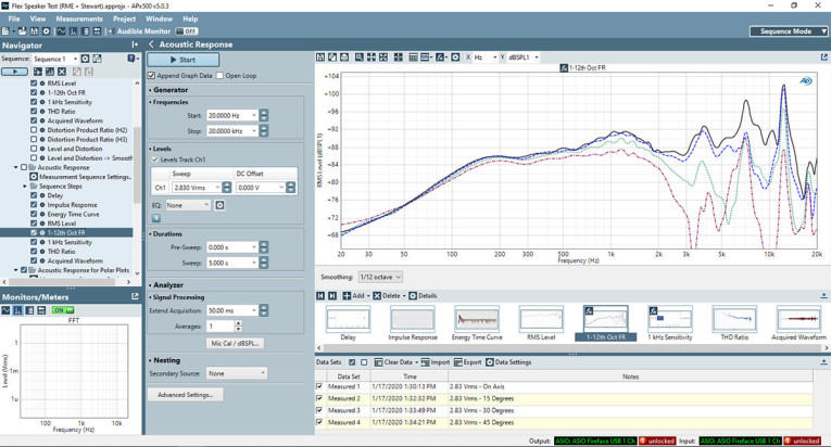
Figure 1 shows the main menu for the APx500 Flex software. While this may look a little complicated, I don’t think the learning curve is very steep, especially if you have been using Fast Fourier Transform (FFT) analyzers for some time, as I have. The navigation menu on the right enables users to choose the type of measurement, SPL, impedance, distortion, and so forth, and you can see that there is a type of display choice below the main graph screen. What I have on the screen shown in Figure 1 is the Acoustic Response selected on the Navigator Pane, and if you look closely, you can see this includes display choices of delay, impulse response, energy time curve, RMS level, 1 kHz sensitivity, total harmonic distortion (THD) ratio, and the acquired waveform.
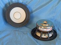
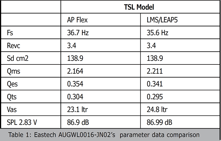
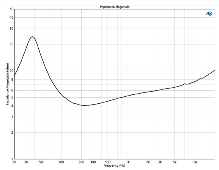
The device under test (DUT) for this exercise was the Eastech's Punktkilde AUGWL0016-JN02, featured in the March 2020 Test Bench, so you can easily compare the results. The first test we performed was to measure the free-air impedance of the Punktkilde 6.5” driver using the AP IMP 1 test fixture shown in the Photo 1. The result, shown in Figure 2, indicates a resonance for the AUGWL0016-JN02 of about 37 Hz. The Thiele-Small (T-S) parameter routine for the APx500 Flex has been very well worked out, and I was able to get parameters from the single measurement, same as I do with LEAP 5. All that was required was to input the Re, 3.4 Ω; the Sd, 137.93 cm2; and the Mmd, 21.4 grams. Then, I compared those parameters to the LMS/LEAP 5 parameters (see Table 1). You can also compare this data to the table you will find in the Test Bench explication of the Punktkilde driver.
Obviously, there were very close results from both the AP T-S parameter calculation routine and the LMS/LEAP system, which I pretty much regard as the “gold standard” for T-S parameter measurement.
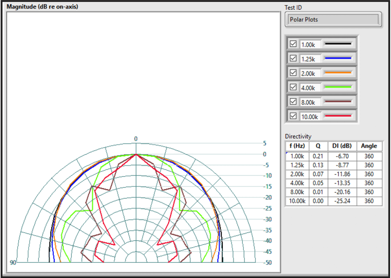
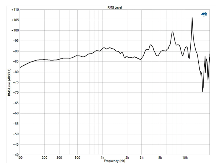
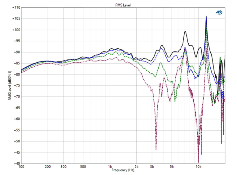
The next task was to get the on- and off-axis frequency response measurements, so we mounted the AUGWL0016-JN02 in the same enclosure as the one used for the Test Bench SPL measurements. Figure 3 displays the on-axis frequency response of the Punktkilde driver. Figure 4 shows the 0° to 45° on and off-axis response. Following this sequence, we then produced a horizontal polar plot. The polar plot routine in the APx500 Flex software is also very nicely worked out, and as with the CLIO software, it enables users to measure just 0° to 90° left and transfer them to the to the 0° to 90° right positions to save time, which is appropriate for a single transducer. The AP Flex’s polar plot has six slots to choose display frequencies on the Polar Plot routing. For this plot, I chose 10 kHz, 8 kHz, 4 kHz, 2 kHz, 1.25 kHz, and 1 kHz (see Figure 5). So, this is a pretty standard polar routine, but I saved the best for last.
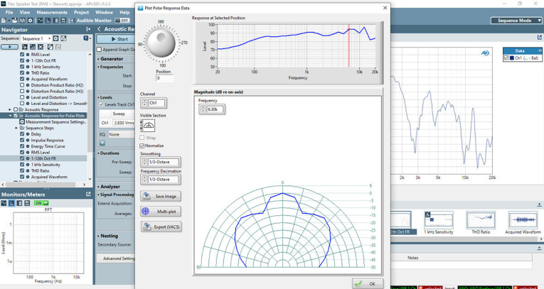
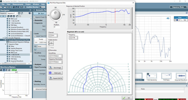
Besides the standard polar plot shown in Figure 5, there is also a utility that is labeled “Response at Selected Position,” which can be seen in Figure 6. If it was physically possible, I would insert a video of this in the magazine, but basically you see a red cursor line on the on-axis response of the speaker. Here, the cursor is set at 6,300 Hz, approximately 1 octave above what would be a typical 3 kHz crossover frequency for a 6.5” driver.
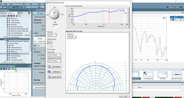
Figure 7 shows the cursor moved down to 3150 Hz. There is quite a lot of directivity in the stop band of a low-pass network at 3 kHz. If we slide the cursor down to 2 kHz (see Figure 8), there is significant decrease in directivity, which is what you want for a good power response on a two-way 6.5” speaker. The trick is finding a tweeter that you can cross that low and still provide good upper harmonic performance. No matter, this is a very useful utility!
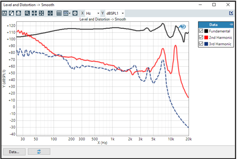
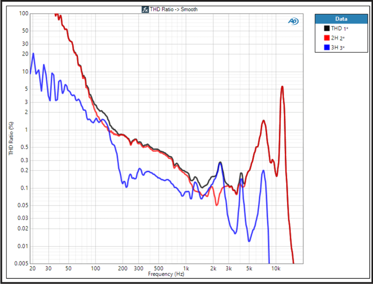
Next we measured the voltage that produced 94 dB/1 m (5.4 V) with pink noise, and then measured the distortion at 10 cm at this voltage level, the same protocol as we use in Test Bench. The results are shown in Figure 9 and Figure 10, which are basically equivalent to the two distortion graphs I show in a single graphic each month in Test Bench, using the Listen, SoundCheck analyzer.
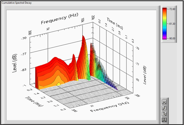
The last measurement we took was the impulse response from the first on-axis frequency response. We turned it into a cumulative spectral decay (CSD) plot, widely referred to as a waterfall plot (see Figure 11). For more information about the Audio Precision APx500 Flex analyzer, read this. We plan to publish a future report on the QC capability of the analyzer in a future issue of Voice Coil. VC
www.ap.com
This article was originally published in Voice Coil, March 2020


