

My first experience with a short XMAX curvilinear paper cone and flat surround pro midrange was the Audax Professional Midrange available from 1980–1990. I reviewed these in an early issue of Voice Coil and later incorporated them into a three-way keyboard monitor that I built for my recording studio. I still have these speakers, but the foam surrounds disintegrated several years ago. Fortunately, Philippe Lesage, the former chief engineer at Audax and these drivers designer formed PHL Audio, which still makes almost the same driver. So, I was able to change the drivers out and not have to make any crossover changes. The Celestion CF0617M also offers a similar format, which is pretty exciting.
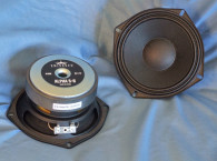
Features for the CF0617M include a four-spoke cast aluminum frame, a light-weight curved profile uncoated Kevlar loaded paper cone, a 2.5” diameter uncoated concave paper dust cap, a 1.75” (45 mm) diameter voice coil wound on a Kapton former with edgewound copperclad aluminum ribbon wire. Compliance is provided by a flat foam surround (such as those found with the Audax and PHL models) and a 4.5” diameter flat cloth spider.
Powering the unit is a 120 mm × 15 mm ferrite magnet, sandwiched between a black emissive-coated shaped front plate and a black coated shaped T-yoke. For cooling, the T-yoke incorporates a 19 mm (0.75”) pole vent with a protective screen. Last, the voice coil tinsel lead wires terminate to pair of chrome color-coded push terminals (see Photo 1).


Testing began with the driver clamped to a rigid test fixture in free air. I used a LinearX LMS analyzer and a VIBox, which produced voltage and admittance (current) curves at 0.3, 1, 3, 6, 10, 15, and 20 V. I had to discard the 15 V and the 20 V curves as they were too nonlinear for LEAP 5 to get a good curve fit. However, it did fit the 10 V curve, which is really impressive for a 6.5” midrange with only 1.2 mm XMAX! I then loaded the five 10 Hz to 20 kHz 550-point stepped sine wave curve pairs (V and I) for each sample. These were post-processed in LMS and the voltage curves were divided by the current curves creating the five impedance curves. The impedance curves each had the LMS phase calculation procedure applied.
I imported them, along with the voltage curve for each sweep, to the LEAP 5 Enclosure Shop CAD program. Since most of the Thiele-Small (T-S) data provided by OEM manufacturers is produced using either a standard T-S model or the LinearX LEAP 4 TSL model, I used the 1 V free-air curves to create a LEAP 4 TSL model. I selected the complete curve set, the multiple voltage impedance curves for the LTD, and the 1 V impedance curves for the TSL model in the transducer derivation menu in LEAP 5 and created the parameters for the computer box simulations. Figure 1 shows 1 V free-air impedance curve. Table 1 compares the LEAP 5 LTD and TSL data and factory parameters for both Celestion CF617M samples.
The CF0617M’s T-S parameter results showed close correlation with the TSL data, and less so with the LTD data. But, most manufacturers use a standard or TSL type model, so this is pretty normal. I use the multi-voltage LTD model for Test Bench because it produces a significantly more accurate simulation of excursion at high voltage levels. I used the LEAP LTD parameters for Sample 1 to program computer enclosure simulations for one sealed and one vented enclosure. This included a 0.07-ft3 closed box with 50% fiberglass fill material and a larger 0.09-ft3 Extended Bass Shelf (EBS) vented box alignment tuned to 114 Hz with 15% fiberglass fill material.
Figure 2 shows the CF0617M’s results in the sealed/vented boxes at 2.83 V and at a voltage level high enough to increase cone excursion to 1.38 mm (XMAX + 15%). This calculation resulted in a F3 frequency of 213 Hz with a QTC = 0.70 for the 0.07-ft3 sealed enclosure and –3 dB = 193.5 Hz in the 0.09-ft3 vented box simulation. Since a midrange such as the CF0617M is likely to be high-passed with an active filter, the CF0617M’s piston range box behavior is generally not that important. I included it because if you are using a passive filter design, it’s helpful to lower the resonance as much as possible.
Increasing the voltage input to both simulations until the maximum linear cone excursion was reached resulted in 113.2 dB at 28.4 V for the smaller sealed enclosure and 115 dB at 22 V input level for the larger vented box. Figure 3 shows the group delay curves. Figure 4 shows the 20/22 V excursion curves.


The CF0617M’s Klippel analysis produced the Bl(X), KMS(X) and Bl and KMS symmetry range plots shown in Figures 5–8. The CF0617M’s Bl(X) curve shown in Figure 5 is fairly broad, especially when you consider the limited XMAX (1.2 mm). The curve is also moderately symmetrical with a small amount of offset. The Bl symmetry plot shows a small 0.2 mm coil-out at the physical driver’s XMAX, and, since it’s not really going to be operating in the piston range, no problem (see Figure 6).
Figure 7 shows KMS (X), which is rather asymmetrical; however, this is just an affectation of the unusual flat foam surround used in this type of device. Figure 8 shows the KMS symmetry range curve, and there is some forward coil-out offset (0.68 mm at the physical XMAX). However for this to be relevant, the cone has to be moving, which in the case of a fourth-order Linkwitz-Riley active high-pass at perhaps 500 Hz, motion won’t be an issue. I am displaying this information for curiosity sake and to characterize the performance of a flat surround (which is only used in the pro sound midrange category). As it is, displacement limiting numbers calculated by the Klippel analyzer were XBl at 82% Bl = 2.7 mm and for the crossover (XC) at 75%, CMS minimum was 1.3 mm.
This means that for the CF0617M, the compliance is the most limiting factor at the prescribed distortion level of 10%. But, even this is beyond the driver’s physical XMAX! If you apply the less conservative criteria of XBl Figure 9 gives the CF0617M’s inductance curves L(X).


Inductance will typically increase in the rear direction from the zero rest position as the voice coil covers more pole area, which is not what you see with this style of motor. From XMAXOUT to XMAXIN, the inductance range is 0.3 mH to 0.28 mH, which is only a ±0.01 mH delta.
Next, I set up the Listen SoundCheck AmpConnect analyzer for distortion measurements with the 6.5” CF0617M mounted in an enclosure using a noise stimulus set to 104 dB (6.7 V) at 1 m. The driver was mounted in free air and the microphone was placed at 10 cm. Figure 10 shows the CF0617M’s distortion curves.


Following the distortion measurements, I again mounted the 6.5” CF0617M in an enclosure with a 12” × 8” baffle for the impulse measurement. This was imported into Listen’s SoundMap software and windowed to remove the room reflections. Figure 11 shows the resulting cumulative spectral decay (CSD) waterfall plot. Figure 12 shows the Wigner-Ville plot.
For the remaining series of SPL measurements, I used the same enclosure as with the impulse response. I used a gated sine wave method to measure the driver's frequency response both on- and off-axis from 300 Hz to 20 kHz with a 100-point resolution at 2.83 V/1 m. Figure 13 shows the CF0617M’s on-axis response, yielding a smooth rising response out to 1 kHz followed by a 4 dB decline to 3 kHz and a broad peak above 4 kHz just prior to the low-pass roll-off. Figure 14 shows the on- and off-axis frequency response at 0°, 15°, 30°, and 45°. The –3 dB at 30° with respect to the on-axis curve occurs at 2.8 kHz, which is in the vicinity of the typical 2.8 to 3 kHz frequently used crossover for 6.5” drivers with 1” domes, but with most horns, somewhere lower than that is appropriate.
Figure 15 shows the two-sample SPL comparisons for the CF0617M, showing both samples to be closely matched through the relevant operating range. Like virtually all the Celestion products I have encountered, the CF0617M’s overall fit, finish, and build quality is very nice.
www.celestion.com


This article was originally published in Voice Coil, December 2015


