Virtual Height Filter for Reflected Sound Rendering Using Upward Firing Drivers
Patent Number: US 9648440B2
Inventors: Brett G. Crockett (Brisbane, CA); Christophe Chabanne (Carpentras, France); Mark Tuffy (Sonoma, CA); Alan J. Seefeldt (San Francisco, CA); C. Phillip Brown (Castro Valley, CA); and Patrick Turnmire (Arroyo Seco, NM)
Assignee: Dolby Laboratories Licensing Corp. (San Francisco, CA)
Filed: January 7, 2014
US Class: 381/307
Granted: May 9, 2017
Number of Claims: 20
Number of Drawings: 23
Abstract from Patent
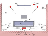
Embodiments are directed to speakers and circuits that reflect sound off a ceiling to a listening location at a distance from a speaker. The reflected sound provides height cues to reproduce audio objects that have overhead audio components. The speaker comprises upward firing drivers to reflect sound off of the upper surface and represents a virtual height speaker (shown in Figure 2 from the patent application). A virtual height filter based on a directional hearing model is applied to the upward-firing driver signal to improve the perception of height for audio signals transmitted by the virtual height speaker to provide optimum reproduction of the overhead reflected sound. The virtual height filter may be incorporated as part of a crossover circuit that separates the full band and sends high frequency sound to the upward-firing driver.

Independent Claims
43. A speaker driver for rendering sound for reflection off of an upper surface of a listening environment, comprising: a driver cone; a cone dust cap affixed to a central portion of the driver cone; and a frame securing the cone for mounting within a speaker cabinet, wherein at least one of the driver cone, dust cap, and frame are configured to apply a height filter having a frequency response curve that is configured to at least partially remove directional cues from a speaker location, and at least partially insert the directional cues from a reflected speaker location, the frequency response curve based on a first frequency response of a filter modeling sound travelling directly from the reflected speaker location to the listener’s ears at a listening position, for said inserting of directional cues from the reflected speaker location, and a second filter frequency response of a filter modeling sound traveling directly from the speaker location to the listener’s ears at the listening position, for removing of directional cues for audio travelling along a path directly from the speaker location to the listener.
46. A system for rendering sound using reflected sound elements, comprising: a speaker placed at a speaker location and comprising a housing enclosing an upward-firing driver oriented at an inclination angle relative to the ground plane and configured to reflect sound off an upper surface of a listening environment to produce a reflected speaker location; and a virtual height filter applying a frequency response curve to an audio signal transmitted to the upward-firing driver, wherein the virtual height filter at least partially removes directional cues from the speaker location and at least partially inserts the directional cues from the reflected speaker location, the frequency response curve based on a first frequency response of a filter modeling sound traveling directly from the reflected speaker location to the listener’s ears at a listening position, for said inserting of directional cues from the reflected speaker location, and a second filter frequency response of a filter modeling sound traveling directly from the speaker location to the listener’s ears at the listening position, for removing of directional cues for audio travelling along a path directly from the speaker location to the listener.
59. A speaker for transmitting sound waves to be reflected off an upper surface of a listening environment, comprising: a housing; an upward-firing driver within the housing and oriented at an inclination angle relative to a ground plane and configured to reflect sound off a reflection point on the upper surface of the listening environment; and a virtual height filter applying a frequency response curve to a signal transmitted to the upward-firing driver, the frequency response curve based on a first frequency response of a filter modeling sound travelling directly from a reflected speaker location to the ears of a listener at a listening position, for inserting of directional cues from the reflected speaker location, and a second filter frequency response of a filter modeling sound travelling directly from a speaker location to the ears of the listener at the listening position, for removing of directional cues for audio travelling along a path directly from a speaker location to the listener.
Reviewer Comments
This is an updated version of a Dolby foreign patent application “previewed” in Voice Coil last year. We promised a review when the US case became available and here it is.
In 2012, Dolby introduced its new, high-channel count, ATMOS spatial rendering system into commercial theaters. The Dolby ATMOS Cinema Processor supported up to 128 discrete audio tracks, using more than 60 loudspeakers in a commercial theater installation. The new level directional control, creating a hemispheric sound scape, is quite impressive, not only in providing more specificity within a set of discrete image angles within the 360° horizontal presentation, the system introduced a new experience of height information and overhead imagery. Even though it was thought by many that it would not be practical to translate this capability into the domestic environment, rumors started almost immediately that Dolby was preparing a home-theater version of the system with a more practical channel count and system requirements—one that could render a convincing 360° horizontal/180° upper hemisphere presentation, emulating a scaled-down version of the commercial system to a substantial degree.
The investigation into understanding the ear-brain system’s ability to localize vertical sound sources in the median plane goes back more than 100 years. Before that time, the prevailing thought was that two ears were required to achieve localization. Some of the earliest studies in the field was accomplished by J. R. Angell and W. Fite, in 1901, in their Psychology Review paper, “The Monaural Localization of Sound.” Their curiosity was piqued by a man who was deaf in one ear, but was still able to localize sound. They performed several tests, comparing the localization ability of a listener with normal hearing to that of the test subject with only one properly functioning ear. They concluded that differences in localizing ability, for complex sounds in binaural and monaural (single ear) hearing, were variations in the magnitude of the minimum threshold for locality, rather than as absolute differences in localizing ability. Pure tones could not be localized in monaural hearing, but complex transient signals were localizable in both cases, albeit with superior angular acuity with binaural hearing.
While there were a few additional studies over the next 65 years, the more complete understanding of the mechanisms involved in the localization of vertical sources in the median plane and the role of the shape of the external ear-pinna reflections, was advanced by numerous authors in the late 1960s and early 1970s. Significant contributions from E. A. G. Shaw in his two primary papers, “Sound Pressure Generated in an External-Ear Replica and Real Human Ears by a Nearby Point Source,” Journal of the Acoustical Society of America (JASA), Volume 44, 1968 and “Transformation of Sound Pressure Level From the Free Field to the Eardrum in the horizontal Plane,” JASA, Volume 56, 1974. These findings illustrated some of the earliest confirmed data that audio source elevation in the median plane was generally represented by an increased output at approximately 7 kHz and a null at 12 kHz (see Figure 3 from the application patent).

Before this time, it was generally understood, that sinusoids and low-passed, complex signals, or noise, below 4 kHz are not localizable as distinct vertical sound sources in the median plane. Research performed in the mid-1970s, by an audio colleague of mine, Robert C. Williamson, found that this is only true if the head is held immobile and the sonic stimuli is moved vertically while perfectly centered in front of the listening subject.
What he discovered was that our heads are constantly making micro movements (similar to a cat’s ears), scanning the audio space around our heads, like an infinite number of microphones, for sounds that are above and below the horizontal plane. Our ear-brain system invokes binaural sensing of vertical information by unconsciously tilting the head sideways and comparing the timing of left/right ear arrivals, allowing much greater precision in vertical image location than high-frequency-based pinna reflections alone. (It was later learned that others had already explored this issue, including Mark F. Davis, now at Dolby Labs, in his graduation thesis at MIT, wherein he did studies with headphones using accelerometers and a computer to reposition the two-channel image information depending on head movements.)
We also did experiments at the time that showed that one could realize more discriminating vertical angle source position detection, if the source was elevated vertically while also being at approximately 45° of left, or right, of center, horizontally. This also allowed left/right binaural scanning of the height information, which was much more accurate, and repeatable, than relying on only the pinna transformations of the high-frequency response. Ultimately, whenever a left/right ear comparison can be used to “find” a sound source, including vertical sources, the ear-brain system is more capable of pinpointing a sound source location.
Binaural sensing is capable of resolving angles of between 1° and 5°. Also, binaural hearing of image placement is more consistent from listener to listener, whereas creating source elevations by way of vertical, pinna high-frequency manipulations is much less consistent among listeners.
Related papers that I remember being particularly stimulating during that period, were two that presented some of the first interesting propositions of applying pinna responses to creating source elevations, and realizing the nature of misaligned loudspeakers, with inadvertent vertical spatialization, were those of P. J. Bloom, “Creating Source Elevations Illusions by Spectral Manipulation,” Journal of the Audio Engineering Society, September 1977 and, C. A. “Puddie” Rodgers, “Pinna Transformations and Sound Reproduction,” Journal of the Audio Engineering Society, April 1981. As often happens, Audio Engineering Society authors were taking the information provided by the earlier pure research of the Acoustical Society of America authors and turning it into proposals for more complete understanding and manipulation of commercial audio products.
In the early 1990s, just as Dolby Digital was becoming the new standard, Brian Aase, an engineer at Carver Corp., investigated the possibility of applying vertical processing to next-generation surround sound signal processors. Using only forward radiating loudspeakers, Aase created a vertical spatialization mode based on pinna transformation information from the research papers listed above. Not having a dedicated “vertical channel” available, Aase developed a spatial detector, which would sense signals that were highly decorrelated, and/or also had channel-trackable movements of a given signal, such as a jet flyover that would start at left-front and move to center, then right-front and finally, into the right-rear-surround channel.
Although never commercialized, the system could be impressive on certain program material, but also it would inappropriately elevate guitars or drums that overly ambitious recording engineers would pan across the channels, creating a rather sensational effect, but not a particularly accurate one (although, I’m not sure what the recording engineers had in mind as a result from that type of recording technique in the first place). So, the system was limited due to not having predictable, dedicated, vertical channels available.
Fast-forward to 2012 and Dolby Labs comes on the scene with, “Atmos,” which incorporates dedicated, height-information channels, significantly advancing the ability to realize well placed, and purposeful, vertical and overhead soundscapes (see Figure 4B from the patent application). Essentially, the technology can be used in at least two modes—one where one utilizes overhead mounted, in-ceiling, loudspeakers (basically a simplified version of the commercial theater systems) or, as covered in the current patent application, standard floor standing or stand mounted loudspeakers, with an additional, upward firing, height information speaker, adapted to receive the height information channel.

The upward firing transducer, can be integrated into, or mounted on top of, the loudspeakers corresponding to the standard horizontal information channels, such as the L/C/R, LS and RS, loudspeakers for 5.1 (or more with greater channel counts). The patent discloses circuits and loudspeakers that are adapted to reflect sound off a ceiling of a listening location in a listening room at a distance from a speaker. The sound reflected off the ceiling surface is received at the listener, as height cues, to reproduce audio “objects” that have overhead audio components. The loudspeaker comprises at least one upward firing transducer to reflect sound off the ceiling, representing a virtual height loudspeaker.
A virtual height filter, based on a vertical, directional, pinna-based hearing model, is applied to the upward-firing transducer signal to enhance the perception of height for audio signals transmitted by the virtual height loudspeaker, to optimize reproduction of the overhead reflected sound. The virtual height filter may be incorporated as part of a crossover circuit that separates the full band and sends high frequency sound to the upward-firing driver or included in the processor providing the preprocessed input signal to the loudspeaker power amplifier channel. Room correction processes can also be used to provide calibration and maintain virtual height filtering in systems that perform automatic room equalization and other correction processes.
The loudspeakers and circuits are configured to be used in conjunction with an adaptive audio input signal and system for rendering spatialized sound using reflected sound elements comprising an array of audio transducers for distribution around a listening environment, where some of the transducers are directed at the listener and others are upward-firing drivers that project sound waves toward the ceiling of the listening environment for reflection to a specific listening area. What Dolby calls a “renderer” is used for processing audio streams and one or more metadata sets that are associated with each audio stream, that specify a playback location in the listening environment of a respective audio stream, wherein the audio streams include one or more reflected audio streams and one or more direct audio streams; and a playback system for rendering, and directing, the audio streams to the array of audio transducer with the one or more metadata sets, and wherein the one or more reflected audio streams are transmitted to the upward firing transducers.
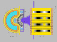
Alternatively, the speaker systems can incorporate the desired pinna-based, frequency transfer function directly into the transducer design of the transducer configured to reflect sound off the ceiling, so the desired frequency transfer function might be incorporated into the design of the transducer diaphragm, the diaphragm dust cap, affixed to a central portion of the transducer, or the frame securing the cone.
The ceiling surfaces are going to vary significantly in terms of reflection angle, diffusion, and absorption, such that the sonic arrival at the listener may differ depending on the environment. So, to supplement the sound that is reflected off the ceiling to the listener, a secondary system is utilized. This secondary system, supplementary, height information cue, can be delivered by the main transducers in the left and right front loudspeakers, with a direct sound path to the listener. The height information that is mixed into the main left and right channel signals is imbued with a frequency response modification that corresponds to the frequency response the ear would hear if receiving an acoustic signal from loudspeaker actually mounted overhead.
There is some speculation that the specifications for the consumer version of the Atmos loudspeaker system will evolve over time to achieve further refinement. Some of these refinements may impact some of the psychoacoustic questions about the system. For example, if one has a reflected signal arriving at the ears from the overhead ceiling reflection, then that signal upon arriving from the overhead angle, will receive the frequency response modifications from the listeners outer ear, pinna transformation of the arriving signal. Then, why would you want to have a pinna-based filter response in the arriving signal? Wouldn’t that “double process” the arriving signal, providing less compelling perception of height? An alternative approach might be to add the pinna transformation to the direct sound signal and delayed by the path length of the ceiling reflection, that way, it can supplement the overhead signal, in case the overhead signal is absorbed or not providing reference level output at the listeners ears.
That said, the system as it is currently delivered, has provided satisfying overhead imaging when users have adequate reflective surfaces overhead, realizing greater 3-D imaging than what was previously available with the best conventional Dolby Surround Sound systems. Kudos to Dolby for bringing a new standard to the marketplace, which is starting to realize the potential of a concept whose time has finally come. VC
This article was originally published in Voice Coil, February 2016.


