Loudspeaker Apparatus
Patent/Publication Number: US20180288522A1
Inventor(s): Teppei Yamada (Tokyo, Japan)
Assignee: Zorzo Co., Ltd. (Tokyo, Japan)
Filed: April 3, 2018
Current CPC Class: H04R 1/227 20130101
Granted: October 4, 2018
Published: November 19, 2019
Number of Claims: 11
Number of Drawings: 19
Abstract from Patent
A loudspeaker apparatus includes at least three speaker units, and a space defining part defining at least two sealed spaces. Each of the speaker units has a diaphragm having two surfaces, and a driver unit for inputting an electrical signal and driving the diaphragm. Each of the sealed spaces has at least two boundary diaphragms. Each of the boundary diaphragms is one of the diaphragms, disposed so that a first one of the surfaces faces inside the sealed space and a second one of the surfaces faces outside the sealed space. When at least one of the boundary diaphragms is driven outward from the sealed space, at least one of the other boundary diaphragms is driven inward to the sealed space. The boundary diaphragms driven outward and the boundary diaphragms driven inward are the same in number, and thereby a volume of the sealed space is kept constant.
Independent Claims
1. A loudspeaker apparatus, comprising: at least three speaker units; and a space defining part defining at least two sealed spaces, wherein each of the speaker units has a diaphragm having two surfaces, and a driver unit for inputting an electrical signal and driving the diaphragm, all of the driver unit inputs substantially the same electrical signal with substantially the same or opposite phases, each of at least two of the sealed spaces has at least two boundary diaphragms, each of the boundary diaphragms is one of the diaphragms, disposed so that a first one of the surfaces faces inside the sealed space and a second one of the surfaces faces outside the sealed space, when at least one of the boundary diaphragms is driven outward from the sealed space, at least one of the other boundary diaphragms is driven inward to the sealed space, the boundary diaphragms driven outward and the boundary diaphragms driven inward are the same in number, and thereby a volume of the sealed space is kept constant.
Reviewer Comments
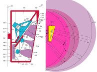
Disclosed is a low-frequency enclosure system incorporating multiple woofers inter-coupled in a manner similar to what is known as an isobaric or compound woofer enclosure. In 1954 in what appears to be the earliest example of its kind, the prolific Harry F. Olson was granted a patent on a dual, compound woofer system, US Patent 2,688,373, “Sound Translating Apparatus” of the basic structure shown as prior art in Figure 1. The same type of system was “reinvented” and popularized by Ivor Tiefenbrun of Linn Corp. in Scotland in 1975, as disclosed in US Patent 4,008,374. Linn coined the label “Isobarik” as the name of the product, from the term “isobaric,” meaning constant pressure. (The misspelling with a “k” on the end is a trademark approach by Linn Corp. of naming most of its products with a “k” replacing the letter “c” in the name of the product.) The “Isobaric” moniker has stuck as the industry name for this configuration. As often happens, the original Olson patent was not cited in the Tiefenbrun patent, so Ivor is often considered the originator of the concept.

The system is most often configured in its most basic form, with a single pair of identical drivers. The original “promoted” notion about how it worked was that as the outer woofer moved inward, the inner woofer was able to also move inward, displacing the same cubic volume as the outer woofer, which was said to create the effect of an infinite volume behind the outer woofer, implying that the cutoff frequency and Qt of the system could be substantially equal to the fundamental resonant frequency and Qt of the driver, which suggests that with the optimal driver, one could achieve a cut-off frequency approaching DC with a small total enclosure volume and very good efficiency…Yahoo, the holy grail! In fact, the marketing department at Linn claimed a passive bass response to below 10Hz in a 75-ltr enclosure, with 87dB sensitivity. Real-world measurements showed that the system’s -3 dB point was 45Hz… close, but no grail.
As it turns out, the better way to look at how the system functions is that the two woofers couple together and operate as single transducer with twice the moving mass, and half the suspension compliance, twice the motor strength, and half the impedance, assuming a parallel connection. One can imagine this more easily by picturing the two drivers positioned face-to-face with a low-mass rod connecting the two diaphragms. Taken further, one can imagine the two drivers merging together with the diaphragms attached to each other, face to face. Ultimately, one can make a single driver with the attributes of the two drivers combined.
Back to the two driver system, the simplest way to calculate the performance is to assume that by combining the two drivers in a isobaric/compound woofer alignment, one can assume that compared to a single driver, the two drivers combined exhibit half the VAS and half or double the impedance (depending on parallel or series hook-up). Given half the VAS, the result is that the same low-frequency performance can be achieved in half the enclosure volume, in exchange for a net 3dB loss in power efficiency (same voltage sensitivity when connected in parallel).
So, in terms of bass bandwidth vs. efficiency vs. enclosure volume, the isobaric/compound woofer system does not provide any advantage, and is constrained by Hofmann’s Iron Law to the same degree a conventional system is. But, that doesn’t mean this type of system is void of advantageous utility. In the most basic form, using two identical drivers, one can synthesize a compound-driver, from a pair of isobaric woofers, to achieve a set of parameters that might be difficult to realize in a single driver package.
The isobaric system may allow one to realize twice the diaphragm mass without collapsing the suspension or causing inferior midrange response. Or, one might want to achieve greater suspension stiffness without causing nonlinearities during extreme excursions or excessive resistive losses. Even doubling motor size might, in some cases, be more costly than using two motors with more standard part-sets. And there may be examples where using two voice coils may provide thermal capability that is difficult to realize in a single larger voice coil without negatively impacting other parameters.
Moving on to the application of non-identical drivers, there are an almost infinite number of possibilities, many of which that are advantageous, but rarely considered for use in isobaric systems. Some examples are: 1) the use of a lower mass, higher efficiency driver externally, in combination with a higher mass driver internally, wherein the inner driver may optionally be low-passed and decoupled at higher frequencies; or 2) the use of a smaller diameter inner driver combined with a larger diameter outer driver, as per some of the original Olson examples from the 1950s. One can imagine a wide range of combinations that may offer useful capability that is difficult to achieve in singular, non-isobaric systems.
There is also the half-active version of the isobaric approach with a powered inner driver and passive outer driver, as explored by Maximilian Hobelsberger in Switzerland, disclosed in US Patent 5,327,504 and US Patent 5,461,676, both titled “Device for Improving Bass Reproduction in Loudspeaker System with Closed Housings” and developed with more sophisticated sensor/feedback systems in US Patent 6,353,670, “Actively Controlled Sound Transducer” by Donald Gasner. By incorporating the active control of the “rear woofer,” the original goal of simulating a zero-stiffness, substantially, infinite volume enclosure environment for the front woofer can be substantially realized. Of course the power requirements for the active, “inner-woofer” are high, as with any equalized low-frequency system, but the passive, “outer-woofer” can embody low mass and high efficiency with reduced power requirements, and there can be additional benefits over a simple, single woofer, equalized system in exchange for system complexity.
There are many sensor and control systems for this type of half-active system, with one of the simplest and most effective developed by Robert Williamson in 1988, which consisted of using a microphone in the common chamber between the two woofers, with any chamber pressure from the frontal woofer causing output from the microphone to drive the amplifier connected to the rear woofer.
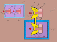
The inventor of the patent application under review here has pursued another approach to the isobaric/compound woofer system. Disclosed is a compound woofer enclosure incorporating more than two woofers, with a sealed chamber between any two of the woofers (see Figures 2-4). His most basic system uses five woofers and some examples have up to 12 woofers, all serially coupled through individual air chambers. It is suggested in the application that all the woofers are identical to each other. Assuming that the coupling chambers are also each of the same internal volume, as is the case in many of the embodiments, the calculation of performance is fairly straightforward.


Even though the inventor doesn’t discuss the outcome in terms of changes in effective VAS one can assume the output will follow the same guidelines as a standard two-woofer isobaric design, with the number of woofers equaling “x” then VAS for a given system will be close to 1/x as compared to a single driver. Any variations impacting the simplest analysis of an isobaric system will tend to come from the acoustic mass and/or the acoustic compliance of the interconnecting chambers, depending on chamber volume and any unmatched performance differentials between the drivers.
The disclosed systems could be used either with the most inner driver coupled to a sealed or vented “primary” enclosure volume, or, with the system operated as an open baffle system by exposing one polarity surface of the diaphragm of the first driver and an opposite polarity diaphragm surface of the innermost driver, to the external environment. The patent application appears to focus more on the latter, open baffle type system.
The advantages discussed are those of keeping constant pressures in each of the chambers between any two drivers (as per the definition of a balanced isobaric system) and coupling all the masses of the drivers such that the system resonant frequency is reduced further with each additional driver, achieving an very low system resonant frequency, with deeper bass being the end result.
While, in general, this result will tend to be the case, one must look at the total enclosure volume required and compare that to conventional systems of the same enclosure volume and compare the bandwidth and efficiency outcomes.
To some degree, the isobaric coupling chamber is a vestigial chamber that adds enclosure volume without having the same benefit as increasing the total volume by the an equivalent amount in a conventional loudspeaker enclosure. Therefore, with isobaric systems, it is most often preferable to have the two drivers be as intimate as possible, with the least amount of coupling chamber volume. With a two-driver isobaric system, the internal volume displaced by the coupling chamber and the internal driver is wasted and considered a loss, compared to standard systems.
In the current invention under review, with a multiplicity of coupling chambers and additional drivers, it would appear that the system would not result in the most efficient use of enclosure volume, particularly in the acoustic suspension and vented versions of the invention. Possibly, in an open dipole baffle version, the internal chambering can be arranged in a manner that keeps the apparent internal volume to a minimum as it is spread across the amount of baffle faceprint dimension that is required for a low cutoff frequency due to cancellation between the front and back waves in the open baffle form of the system. In the case of open baffle dipoles, maximizing surface area and reducing mass are design priorities. The invention tends to go in the opposite direction, by increasing total moving mass for a given diaphragm area radiating into the external environment.
It is possible that with some unique combination of differentiated drivers, drive signal, or unique configuration of the invention, (not mentioned by the inventors) that it may offer a compelling advantage, but it is not currently clear to this reviewer as to how this high driver count version of isobaric compound woofer architecture offers any significant advancement over the many possible configurations of the basic two-driver isobaric woofer system. VC
This article was originally published in Voice Coil, April 2019


