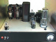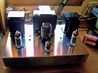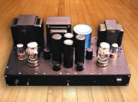
After searching for a while, I decided to build an SE project with the 12L6s I had found. Now, first of all, don’t get excited and think that a 12L6 is the same tube as a 6L6 with a different heater rating! This tube is in the same basic category as a 12W6, a 12CS5, a 12DB5, and except for the heater a 6DG6. The normal operating voltages are 200V DC on the plate and 125V DC on the screen. It was frequently used in many old television sets as the audio output tube and is capable of nearly 4W of single–ended power. (I can still remember the great sound that came from an old Zenith set my parents used to own.) The mini-sized amp in this article is only about two-thirds the size of my “little amp” project (aX 12/01) and uses a very simple circuit.
I used a 12SN7 for the voltage amplifier, and coupled each 12L6 to a Hammond output transformer, which is small and inexpensive. If you like to experiment, you can even modify the circuit to use other tubes which will deliver a different sound and more power to your speakers. You’ll find some of the parts at Radio Shack, while others are available from Mouser and Antique Electronics Supply. I used a black ABS plastic box for my amp, but if you prefer to use a Hammond aluminum chassis then a #P-H1444-16 will do just fine.
The plastic box has been a pleasure to work with. It was easy to drill and punch and leaves no rough edges or sharp filings. The box is even textured with a sort of wrinkle coat finish that doesn’t require any painting (Photo 1). It measures only 9 × 6 × 3″ and held all of the components of the power supply and amp quite nicely.
Now, some hobbyists may shy away from plastic, fearing that the heat generated by the vacuum tubes would cause a problem, but I found that this amp has a low heat output and the integrity of the box wasn’t bothered in the slightest. It’s hard to cause a short circuit with a test probe and it’s difficult to get zapped if you’re touching the chassis when testing!
This easy-to-construct project should take about 16 to 20 hours to complete and can be a great learning experience, especially if you are a beginner in this fascinating hobby. If so, it can be a great confidence booster and can perhaps help you to better understand basic vacuum tube circuits. So, good luck and have fun!

Getting Started
Start by obtaining all of the parts necessary to complete the project, because this will allow you to properly lay out the chassis in the manner you desire. Drill and punch all of the holes needed to attach everything to the box. If you wish to copy the design of this amp, you will find that the topology will come out just fine. If you do use a small plastic box, as I did, just remember to be careful with the component arrangement so you don’t cause any shorted connections, and try to insulate the bare leads where possible.
If you look closely at the parts layout in Photo 2, you will see that the sockets and terminal strips are spaced to allow for easy wiring hookup. The choke, heater transformer, filter capacitors, and the time–delay module tend to make it look a bit more crowded, but this was the only way I could fit all of the parts inside. If you use the Hammond aluminum chassis, you will have much more room to mount your components.
I installed everything on the bottom of the chassis top plate first and added the filter capacitors last. This gave me lots of space to work in when connecting the heater and amp circuit wiring. The rear panel has the speaker binding posts, input jacks, primary circuit fuse, and the off–on switch installed on it and also has the power cord exiting through a hole with a rubber grommet in it.
The front panel contains the volume controls, complete with aluminum knobs, and a cool-looking blue LED pilot light. I didn’t place the main power switch on the front panel for the sole reason of maintaining its clean look with only the control knobs and LED showing.
The chassis top has the HV power and output trannies and, of course, the vacuum tubes arranged in an open, uncluttered fashion. I turned the Hammond #125CSE outputs at a 90° angle to eliminate any magnetic coupling with the high-voltage Hammond #T261M6 transformer. I painted all of the transformers to match the chassis box color and then used brass screws to mount them and the tube sockets to the top plate.
I used an in-line type of fuse for the B+ circuit inside the chassis area. I like to always use a fuse in the HV rail to prevent the destruction of the B+ transformer in the event of a short in one of the filter caps or similar problems. Wire in the heater circuit first and use the hookup method shown in Fig. 1. This allows equal voltage to all of the tube heaters, even though these tubes don’t use much heater power.
The actual total draw is only 1.50A. Mount both of the 12L6 sockets in the same direction (key to the left, bottom view), because this will assist you in your wiring layout of both channels and will reduce the confusion that can occur when having to “flip-flop” the wiring scheme. Once you know that you have one channel correct, simply move over to the next one and complete it.

The Circuits
The single–ended circuit I used here is really simple and contains only the parts necessary to complete the amp and give a smooth, warm, and a somewhat surprising sound. This easy-to-build, low-parts-count circuit has been used on many single–ended amplifiers over the years and is capable of delivering a decent hi-fi sound without the use of “high end” components. It is also a very trustworthy and trouble-free design that should last for many years.
I have included some notes on the sound quality of the amplifier at the end of this article. One-half of the 12SN7 is used as the voltage amplifier for each channel. The input signal enters through the RCA jack (J1), then travels through the volume control, which controls the amount of voltage that reaches the grid of a triode section of the 12SN7. The boosted voltage is then coupled by way of capacitor C2 to the grid of the power tube, which is the final amplification stage.
The Hammond 125CSE couples the plate of the 12L6 to the speaker and matches the plate resistance to the voice-coil resistance, in this case 8Ω. If you are using the 12L6s, as I did, with 8Ω speakers, then use the color codes you see on the diagram (Fig. 1). The 12L6 receives its cathode bias by way of resistor R8, which is bypassed by capacitor C3. I chose not to use any feedback from the output secondary windings, but, if you wish to experiment, feel free to try to tailor the sound to your liking.
The power supply uses a choke–input filter setup in order to obtain the 200V of B+ needed. You will see on Fig. 1 how the choke is wired into the circuit with the first filter capacitor installed after the coil. The initial resistance of the Hammond #158Q choke is around 110Ω and supplies the drop in voltage (under full load) needed to allow 203V DC to enter the primaries of the output transformers.
The final reading at the plates of the 12L6s is 195V, which is close enough. (All of the operating voltages are shown in Fig. 1.) The B+ for the screens is set to the correct value by means of resistor R10. (You can disregard the two 10Ω resistors in Photo 1 that are paralleled and tied into the plates of the 12L6s; these were part of an experiment.)
Most single-ended amps are more susceptible to hum from their power supplies than are push–pull amps because push–pulls can cancel out the hum in their circuits, so I used a large value capacitor in the B+ rail. Its rating is 680μF × 250V. I had it in stock and it works very well in keeping the hum to a minimum, but your amp might do OK with a lower value so you could start out with around 200μF and add more if needed. It also helps to use DC on the heater of the 12SN7. I found that I needed to place my ear 12″ away from the speaker to hear any hum, and since that is not my usual listening position, it doesn’t bother me at all.
The blue LED pilot lamp on the front panel is the “ultra bright” type, so I used a dropping resistor to reduce its output brilliance. I didn’t want it so bright that it would overpower the glow of the heaters in the vacuum tubes, especially the 12L6s, which have a really nice glow about them. I used a 100k ¼W resistor to obtain the perfect amount of light from the LED, and it is a great indicator that the amp is on when you first glance at it from across the room.
The 12L6 has a heater that was meant for “string series” operation, and it needs a full 10 to 12 seconds to warm up. Even though the tubes used here are inexpensive, it is against my better judgment to allow the B+ to hit any tube before the cathode warms up sufficiently, so I installed a time delay relay in the primary circuit of the B+ transformer.
This little modular relay is sealed in epoxy, about 2″ square, and has an adjustable time capability. I picked it up from a local appliance parts store, but if you have trouble finding one, you can always use a separate switch for the transformer. Just remember to wait about 30 seconds before turning it on. I can’t even hear the slightest pop or thump when the B+ is applied to the tubes, which is about 30 seconds after the main power switch is engaged. I used a Radio Shack transformer, rated for 12.6V at 3A, for the heaters. I have found over the years that all of their small transformers have performed quite well, and I’ve never experienced any mechanical hum or vibration from them. Not bad for cheap trannies.

I used a couple of terminal strips at the socket for the 12SN7 to keep the wiring fairly neat, and I used the socket terminals numbers 1 and 6 on the 12L6s for additional connection points. This is possible because there are no connections to the tube at these pins. Be sure to use shielded cable when wiring the input jacks to the volume controls and use good grounding and soldering techniques.
I used some bare copper wire for all of the grounded connections, then attached it to the ground at the input jacks. The power transformer used here also has a 6.3V winding; so if you choose to try other tubes for this amp, such as a 6V6, a 6Y6, or a 6BQ5, then you can wire the power supply as the correct input load type and then reduce the B+ voltages to their proper values by means of dropping resistors of sufficient value and power ratings. Speaking of power ratings, I used a 10W resistor for the cathode bias resistor to prevent heat buildup under the chassis. I realize that a 5 watter would probably have been OK, but why take the chance?
By the way, I used metal film resistors throughout the amplifier circuit. If you find that the sound from your amp is a little on the “bright” side, you might try some carbon resistors to take the edge off and mellow it out. I used “Auricaps” for the coupling capacitors because I love the clean way they sound, but if you want to save some money then use the “orange drop” capacitors available from Antique Electronics Supply.
After you have finished the assembly and wiring of your amp and are sure that everything looks OK, power it up with all of the tubes in place. Be sure to have your speakers connected. After the amp has warmed up for a couple of minutes, use a DVM to measure the operating voltages at the points shown on the diagram in Fig. 1. Of course, you will do this with the negative lead from the meter to a ground connection point and then use the positive lead to touch the reference points noted on the diagram.
If you are using test leads with long pointed bare metal ends, it would be a good idea to slip a piece of heat-shrink tubing over the tip and leave only a small portion of it exposed. Shrink the tubing with a heat source and you will have a much safer test probe. Be careful here because even though the B+ is only around 200V, it can still get your attention if you are careless! If your meter readings are within 5% or so of the ones on the diagram, you can be fairly sure that all of the circuits are performing OK.
In case you do find a problem such as a bad solder joint causing an erroneous reading, power the amp down, discharge the power caps, and correct it, power up again, and take another reading. If the terminal on one of the tube sockets needs resoldering, be sure to remove the tube first! Now turn on and activate the audio source that you are plugging into the input jack (CD player, FM tuner, tape deck, and so on) and adjust the volume controls to balance the output of both channels as desired. With the individual level controls on this unit, no balance control is required. You are now ready to enjoy the sound of your new single-ended amplifier. Incidentally, this small amp takes up less than a square foot of shelf space, is very lightweight, and uses only 45W of electrical energy.
Note: If you like to experiment with power supplies and want to use all Radio Shack transformers, you could use a backwards wiring technique with a second heater tranny and wire it as a voltage doubler type of circuit. Then adjust your B+ voltages accordingly. Most experienced hobbyists already know how to construct this type of power supply. In this article I’m not including this information because I’m trying to keep the project as simple as possible.

The Sound
I’m not going to try to tell you that this little SE amplifier will blow your socks off and sound better than any single-ended 2A3 ever could. That would really be a bit of a stretch! What I will say is that this amp really surprised me with its sound and the way it handles most music. I was not ready for the warm, smooth sound when I first started it up. Most amps require a fairly good break-in period before sounding their best, but this little guy came out of the corner swinging! First of all, the specs on the Hammond output trannies must be really conservative because the fullness of the music I heard you can only hear from bigger iron.
The stated frequency range is from 100Hz to 18kHz, but in no way does this amp sound puny or lacking in sonic energy as you might expect. It has a real “peppy” and “happy” sound! Except for music with a lot of very low bass passages, it seems to handle whatever I put into it with relative ease. It is well known that the output transformer has a very large effect on the final sound of any tube amplifier, and all I can say here is, “Thank you, Hammond engineers!”
The midrange is very open, and the treble, though somewhat rolled off above 12kHz, is downright smooth. The bass is very good, although not as good as my 6550 SE amp (aX 9/01), as you would expect, but when I played Holly Cole’s album “Blame It on My Youth,” track #4, the plucked bass sounded full and fairly solid. Her voice came through crystal clear and natural.
Another surprise was the violins and bowed basses on the Philips album #416361–2, by John Williams and the Boston Pops. The bowed basses on track #2, “Clair de lune,” really filled up the room although not a very large room and then the goosebumps came. When track #4, “The Swan,” started, Martha Babcock’s wonderful cello almost floated me away to another time and place. Another album that I used to test the performance was what many audiophiles consider one of the best recordings of plucked bass sound of all time, the Three Blind Mice CD #GS–CD006. Tracks #5 and #8 came through this mini-sized amp sounding very natural, and, while not earthshaking, were notably accurate. For such a small low power amp, the only words I can find to sum up the experience are “WOW, Big Surprise!”
Originally I used the GE brand of 12L6 tubes, which you see in Photos 1 and 3 and are date-coded 1962. They sounded great, but after Steve at AES sent me a pair of “Dumont” branded tubes, dated 1971, and I gave them a three-hour break-in period, they gave me an even better quality of sound.
In Photo 3 you will see the amp in use with a Dynaco CDV-1 vacuum tube CD player with 2.0V of output. This CD player drives the amplifier to full output with both volume controls at their 1:00 position and with minimum distortion. (Actually, I never pay any attention to distortion in single-ended amps.) Also in the photo, you will see the amp driving the Parts Express #BR–1 speakers. Although not really high-efficiency speakers, they are playing very loud with the amp’s volume controls at the 2:00 setting, and they sound very nice.
If you have some good full-range speakers that are at least 90dB efficiency, I think you will be satisfied with the results you will obtain from this amplifier. If you choose to become deeply involved in this project and wish to achieve as good a sound as possible, you can upgrade to a bigger (and better) single-ended output transformer. There are quite a few on the market now. You can always use the “high end” tube sockets, resistors, wiring, volume controls, and other such components. The possibilities are almost endless.
Again, this amp project doesn’t really take very long to complete, and I’m sure that someone out there much wiser than I can probably improve on it. So, take your time, don’t rush, enjoy yourself. Follow the diagram closely, and, when finished, your version of this amplifier should work when you first power it up, and give you many hours of enjoyment. The finished product will also give you the pride of knowing that you built it yourself. Happy building and happy listening.
This article was originally published in audioXpress, April 2004.


