As the paradigm progressed, additional low-mid and high-mid (and more recently, super-high frequency) speakers were added to some designs, though, as Paul Klipsch observed, “with no new contributions to the nomenclature.”
As the loudspeaker industry matured, most manufacturers have standardized upon two-way and three-way speakers, additional splitting of the spectrum has been found to contribute to both crossover design issues and cost, but little, if any, improvement in the sound or marketability of the speaker. Whether a speaker is designed for professional sound reinforcement, studio monitoring, or home audio, its sound quality and durability are heavily influenced by the extent to which the woofer, tweeter (and mid, if there be such) play well together. While some aspects of optimally choosing these drivers are obvious, one or two criteria are more subtle.
These different aspects are discussed in the paragraphs that follow, but the order in which they are discussed should not be taken as significant. Since many of these aspects interact, the selection process is an iterative one.
The Low-Frequency Driver
Maximum SPL—Electrical Limit: The SPL of a speaker system, as of its drivers, is specified as dBSPL at 1 m, usually with an input of 2.828 V (nominally 1 W at 8 ). Knowing the desired maximum sustained sound pressure at a specific distance and the approximate acoustical environment, the designer can work backward to arrive at the appropriate driver specification. For example, a recording studio monitor (not a control-room monitor, as these have different issues) might be expected to produce a maximum average of 95 dBSPL at a distance of 3 m on-axis in a room having a reverberation time under 1 s. For most studio monitor speakers, 3 m is far enough away to be considered as being in the far field.
Depending upon the studio dimensions, the critical distance may well be within the 2-to-3-m range, so the decrease of sound level may be about 3 to 5 dB per doubling of frequency.
However, using free-field conditions as a worst-case limit, a level of 95 dBSPL at 3 m corresponds to a level of about 104.5 dBSPL at 1 m, so the combination of low-frequency driver sensitivity and electrical power handling must allow at least this much level at 1 m, throughout the frequency range to be used in the system.
Maximum SPL—Mechanical Limit: The mechanical limit of SPL is imposed by the excursion limit at which physical driver damage can occur. For practical considerations, the specification xmax is used, which includes both magnetic field and mechanical excursion limitations. The required excursion depends upon the diameter, Qtc of the driver, and the cabinet design—being smallest for low-frequency horns, longer for transmission line speakers and vented boxes using common alignments, and longest for closed boxes. Standard references such as Vance Dickason’s Loudspeaker Design Cookbook discuss methods of determining the needed xmax.
This involves converting the needed SPL at 1 m into acoustic power, then finding the necessary volume displacement of the low-frequency driver’s cone. This volume displacement is then divided by the cone area to yield the needed xmax.
Frequency Response: Driver frequency response and crossover frequency are to some extent a chicken-and-egg question. Since even very good speakers have differences in coloration, the crossover point should ideally be chosen so that it does not occur in a range in which the ear is most sensitive to naturalness of reproduction. We are most likely to notice a change in coloration of sound if it occurs in the middle fundamental voice range. Thus, most designers choose to cross from woofer to midrange somewhere above 1 kHz.
This is still in the voice range, but above the fundamental voice frequencies. Often, the choice of crossover frequency is at least partially dictated by the available drivers. In either case, the woofer should possess a relatively flat response to somewhat above the crossover frequency. If a first-order, lowpass filter is used in the crossover, and 1-dB flatness is desired, the woofer response should be within about 2 dB of flat up to at least twice the crossover frequency. For a second-order crossover, the woofer response should be within 2 dB of flat up to a half-octave (roughly 40%) above the crossover frequency.
For a third-order crossover, that level of flatness should extend to at least one-third octave (roughly 26%) above the crossover frequency.
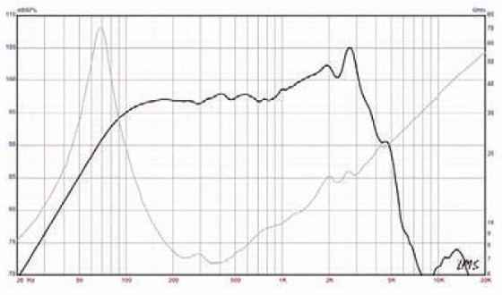
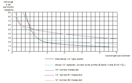
Figure 1 shows the frequency response of an Eminence Delta 12LFC professional woofer. A first-order crossover applied to this woofer should optimally occur at or below 600 Hz; the second-order at about 850 Hz; and the third-octave at about 960 Hz. Optimum crossover frequency also depends partially upon directivity issues, and will be discussed later.
Size and Directivity: Maximum required excursion of a driver is inversely proportional to the cone area, thus doubling the diameter of a speaker (quadrupling the cone area) reduces required excursion by a factor of four. This means that larger speakers can show an increase in the possible electroacoustic conversion efficiency of the driver as well as a decrease in both amplitude- and frequency-modulation distortion, both of which increase with excursion. However, larger drivers tend to cost more and require larger enclosures, plus the directivity of a driver depends upon its diameter.
The Midrange & High-Frequency Drivers
Maximum SPL—Electrical Limit: Tests made from the late 1920s forward(1) indicate that for most musical ensembles, SPL peaks somewhere in the 200 to 600-Hz range, and decreases at a rate of about 20 dB per decade above that frequency. This is the same as saying that SPL decreases with increase in frequency at a rate of 6 dB per octave. Thus, if the electrical power rating for the woofer is multiplied by the ratio:
600 Hz/(high-pass crossover frequency of the midrange drive)
a conservative rating for the needed electrical power rating of the midrange driver can be obtained. This approach is often used by manufacturers who specify a “system power” for midrange and HF drivers, rather than a continuous long-term average power rating. The rating is conservative because the octave just above the crossover frequency is statistically likely to contain the most power of any octave in the driver’s passband, and at the low end of that octave, half or so of the total power in the octave, including the crossover frequency is fed to the woofer.
Maximum SPL—Mechanical Limit: The calculation of required xmax is done in the same way as it is for a woofer, except that the frequency used in the calculation for the mid driver is the crossover frequency, not the low-frequency limit of the system as for the woofer. Some manufacturers specify a maximum electrical power at a certain frequency rather than listing xmax for midrange drivers. This specification can be converted for use with other frequencies if you remember that the acoustical power is proportional to the excursion and the excursion is inversely proportional to the fourth power of frequency. Thus, a midrange driver rated as 25-W continuous average power (10 W above 2 kHz) could handle a brief peak of 160 W at twice 2 kHz = 4 kHz (i.e., 24 × 10 W) without exceeding xmax, although (1) the 25-W electrical limit would still apply to the long-term average power, and (2) depending upon the construction, a 160-W pulse could open the voice coil. As an example, the Eminence Alpha-6C, a 6.5” midrange driver, has an xmax of 3.5 mm, which corresponds to an SPL of about 105.5 dB at 1 m at 140 Hz.
Frequency Response: The frequency response considerations outlined earlier for woofers also apply to mids and tweeters, except that a good midrange speaker must have reasonably flat response both below and above its intended passband, and a tweeter should have pretty flat response below its passband. The factors given for crossovers of various orders apply to mids and tweeters also. For calculating the flatness limits below the crossover frequency, 1/2 octave below the crossover frequency is about 70% of fc while 1/3 octave below is about 80% of fc.
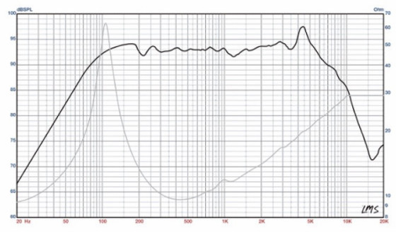
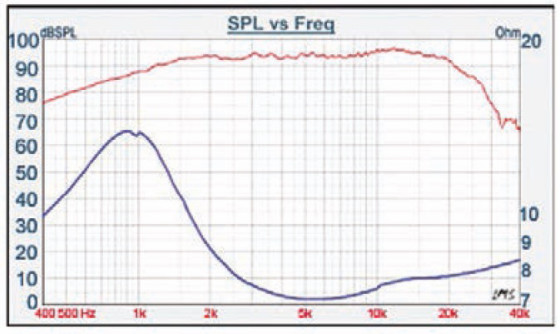
Figure 3 shows the frequency response of an Eminence Alpha-6C cone midrange driver. This model has a reasonably flat frequency response from about 100 Hz to 4 kHz, making it useful with a second-order crossover from about 140 Hz to 2.8 kHz.
Figure 4 shows the frequency response of a Tang Band 28-1582S 1” dome tweeter. Based only upon frequency response, this unit would seem suitable for use with a second order crossover having a crossover frequency of 2.8 kHz or greater. The manufacturer lists the air gap height as 3 mm, although the xmax is not specified. As a rough estimate, we can assume about a 10% overhang. If the methods discussed earlier are used to determine maximum needed excursion for the required SPL at 2.8 kHz, the suitability of a 2.8-kHz crossover can be determined. In this case, an excursion of 0.15 mm at 2.8 kHz works out to about 107 dBSPL at 1 m, which is below the maximum-power SPL of 114 dB at 1 m, but a 2.8-kHz crossover frequency may be fine, depending upon the necessary maximum SPL of the tweeter as used in the completed system.
Size and Directivity: Numerous articles have been written discussing whether a speaker should have uniform total sound power output with frequency or uniform SPL on axis. Since real acoustical sources become more directional as frequency increases, a speaker having uniform sound power output with frequency would be a real challenge to create unless the uniform sound power radiation was achieved by increasing the on-axis SPL with frequency to compensate for decreasing off-axis sound radiation at higher frequencies.
Furthermore, we are accustomed to “room sound” being bassy in character, so we ignore the increase in perceived bass caused by lack of speaker directivity at lower frequencies.
However, it has been observed that multiway speakers do sound better if the decrease in total sound power output with frequency occurs smoothly rather than in abrupt jumps.
This means that the directivity of a speaker system should not change abruptly at the crossover frequencies. Since the change in driver diameter from woofer to midrange to tweeter is necessary, we must find creative solutions to the problem of maintaining smooth transitions in directivity.
Woofer manufacturers seldom specify the variation of the directional characteristics of their drivers with frequency, so it is left to the speaker system designer to make directionality measurements, unless the approximate values derived from Figure 2 are deemed accurate enough.
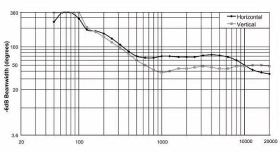
Smooth transition of directivity is much easier to achieve with horn-loaded midrange and tweeter drivers. Figure 5 shows the directivity of an Electro-Voice EVH1152D/64 two-way 15”-plus horn speaker system that accomplishes a smooth directivity transition. Since the mid/high driver is loaded by a constant-directivity horn, the directivity becomes more-or-less constant above the crossover frequency.
But, it transitions quite smoothly from the cone woofer’s increasing directivity with frequency to the constant directivity of the horn.
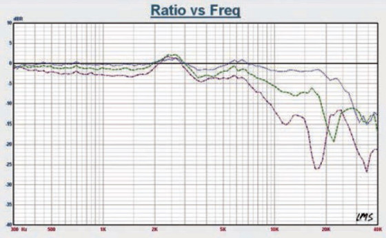
In a speaker using only cone drivers, smooth directivity transition is much more difficult to achieve, since the midrange and tweeter are usually nearly omnidirectional at crossover. Whereas, the woofer usually has some, and perhaps substantial directivity at the crossover frequency. It is a common misconception that dome mids and tweeters radiate as radially vibrating hemispheres. However, the fact is that they radiate pretty much as pistons and have the same directivity issues as cone drivers. A comparison of high frequency (greater than 10 kHz) on- and off-axis responses of dome tweeters tested in Voice Coil’s Test Bench column will clearly reveal this fact (See Figure 6).
One method that has been used to smooth the directivity transition in systems using cone drivers is slot loading, which is a technique in which the opening in the woofer baffle is restricted so that it appears acoustically smaller that it otherwise would, thereby widening the beam width in the upper
portion of the woofer’s range. Some of the highly-regarded
BBC monitoring speakers used this approach.(2) Slot loading
acts as an acoustical low-pass filter, a fact that must be taken into account in crossover design.
Sensitivity: Although attenuators can be included in crossover networks, network design is simplified if the woofer and tweeter have essentially the same sensitivity.
Let’s consider a worked example. If we were to design a three-way speaker system using the Eminence Delta 12LFC woofer, Eminence Alpha-6C midrange, and Tang Band 28-1582S tweeter, with design objectives of 95 dBSPL longterm at 4 m on axis, 90° × 90° beam width (45° × 45° half- angle), assuming the use of a second-order crossover and a vented cabinet having an f3 of 70 Hz, we have the following considerations:
Frequency response:
• Woofer—cross anywhere below 850 Hz
• Midrange—cross over anywhere within the range of 140 to 2800 Hz
• Tweeter—cross over at or above 2800 Hz
Electrical Power and Excursion: For 95 dBSPL long-term, we will want to add at least 10 dB of headroom, so our peak SPL at 4 m should be 105 dBSPL, which will require 117 dBSPL at 1 m.
Woofer—at maximum excursion (xmax of woofer is 4.8 mm), the woofer can produce 118.3 dB at 1 m on axis, using a vented cabinet. This will require an electrical input of 251 W, well below the 500-W rating.
Midrange—at maximum excursion, the midrange can produce 117.5 dBSPL at frequencies above 210 Hz, but the Alpha 6-C is only rated at 200-W program, and it would require an electrical input of 251 W to produce 117 dBSPL. Since the highest average power for most music programs occurs below 600 Hz, if we choose a crossover point from the woofer to the midrange of 600 Hz, we can protect the mid from some of the power.
Tweeter—at maximum excursion, the tweeter can produce 106.8 dBSPL at 1 meter, using about 25 W, which is below the rated peak power. However, since the average SPL of a typical music signal at a given frequency decreases at a rate of 20 dB/decade above 600 Hz, for a crossover frequency of 2800 Hz, the tweeter will only need to handle about 11.5 W (below the rated long-term power of 12 W) and produce about 103.6 dBSPL.
Directivity: Using the curves in Figure 2, we find that the half-beam width of the 12” woofer is over 90° at 600 Hz, dropping to about 90° at 850 Hz. The half-beam width of the midrange driver is over 90° at either of those frequencies; theoretically, the driver is essentially omnidirectional at either.
At 2800 Hz, the midrange driver has a beam width of about 95°. The tweeter’s theoretical beam width is greater than 180° up to about 10 kHz, although in practice, off-axis performance will probably not be quite that good, as illustrated in Figure 6.
Putting It Together
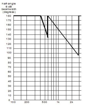
Probably the crossover frequency most likely to draw attention to the change of timbre from woofer to midrange is 1 kHz. Thus, since we cannot achieve a smooth directivity transition across the crossover frequencies in this case, we can choose our lower crossover frequency as 600 Hz, we can help keep the mid safe from overpowering and keep the lower crossover as aurally unobtrusive as possible. In like manner, if we cross into the tweeter at as high a frequency as we can, we will protect the tweeter, but for our example design, crossing above 2800 Hz would require a different choice of midrange driver, or a steeper crossover from mid to tweeter that would to allow us to cross closer to the 4-kHz “flat response” limit. Again, smooth directivity transition is not an option with these drivers. Figure 7 shows the theoretical directivity of our design at this point. The directivity anomalies will not be very audible on-axis in an acoustically dead room, but the greater the reverberation time of the room, and/or the farther off-axis the listener is, the more likely the speaker is to sound weak in the upper midrange. The smaller variation between 400 and 600 Hz will be much less noticeable.
The beam width narrowing below 400 Hz could be reduced by the use of a smaller woofer, but doing this would entail other design considerations that would have to be evaluated.
Alternatively, slot loading could be employed, but such a design is beyond the scope of this article. If a constant-directivity horn were used for the tweeter, the beam width could be made to level out above the 3.2 kHz crossover, making the upper midrange sound less thin by comparison, either off-axis or in a reverberant room. Even though we were not able to keep beam width constant, or even keep the transitions smooth, we have achieved a beam width greater than the minimum required for the whole passband of the speaker.
References
(1). L. J. Sivian, H. K. Dunn, and S. D. White, “Absolute Amplitudes and Spectra of Certain Musical Instruments and Orchestras,” Bell System Technical Journal, October 1929.
(2). H. D. Harwood, “The Design of a Low-frequency Unit for Monitoring Loudspeakers,” BBC Engineering Division Monograph # 68, July 1967.
This article was originally published in Voice Coil, January 2012.