Why Do We Need A Preamp?
The most visible functions of a preamp are to provide source signal selection (e.g., CD player, phono preamp, and so forth) and volume control for your audio system. A preamp doesn’t really need very much voltage gain; in fact, some designs, called “passive preamps,” don’t have an amplifier stage at all. There is much to be said for these designs after all, with no gain stage and only switches and passive attenuators in the signal path, the noise and distortion performance is hard to beat. So why would we need an amplifier?
The biggest problem (for me) with a passive preamp is that its outputs have a relatively high source impedance, and one that tends to vary substantially depending on the position of the volume control and the output impedance of whatever is driving it. This works OK as long as the load (the amplifier) is well behaved, with a high load impedance, and there isn’t too much capacitance in the amp or interconnect cable.
In my system, this isn’t usually the case. I typically have several power amps connected, with only one pair in use at a time. Often I also have a headphone amp or two plugged in. Each of the loads is usually pretty benign, but when you parallel several along with their interconnect cables you wind up with a load that really needs to be driven with a low source impedance to sound good. Many amplifiers also aren’t all that well behaved. People assume that a class A1 load (such as the input of their power amp) is always a high impedance. At DC, this is usually the case; but the effective input capacitance can be quite high, especially in designs that use high-gain triodes in the input.
Tube Preamp Designs
So, you want a preamp, and you’re going to build it with tubes. You can choose from several common design topologies used in tube preamps, as well as some unconventional ones. The oldest preamp designs are essentially small single-ended power amplifiers.
They use a gain stage with an output transformer as the plate load of a tube, with the turns ratio set to provide a high load impedance to the plate, and a low output impedance. Many people believe that this is the best type of circuit, partly because it doesn’t use any coupling capacitors in the signal path. The downside is that it’s expensive to implement a good line output transformer can cost several hundred dollars, and the cheap ones don’t perform very well.
A “classic” design that’s typical of 1960s hi-fi equipment uses a high gain triode such as a 12AX7 as a grounded cathode amplifier, coupled to another triode acting as a cathode follower. Without negative feedback, this type of circuit has very high gain (around 80) and distortion, and high output impedance. Lots of overall negative feedback is used to get the gain down to close to 10 or 20, which reduces distortion and output impedance. Though it measures well, I don’t like the way this type of circuit sounds. I suspect that I’m hearing the large amount of feedback that increases higher-order harmonic distortion.
A similar design uses a medium-mu triode such as the 6SN7, and no feedback. This type of amplifier, if properly designed and not overloaded, sounds pretty good to me. It has low output impedance and distortion, but cannot deliver lots of current to the load (current delivery is limited by the amount of current flowing through the tube, regardless of output impedance).
Cathode followers are not without their problems (and critics), though. I’ve had problems with the heater-cathode interface inducing noise, and even insulation breakdown, since the cathode is operated at an elevated voltage.
Another common preamp stage uses two triodes in an SRPP circuit, with the triodes connected in series and the upper tube acting as both a cathode follower and a plate load for the lower tube. These circuits can achieve very low distortion and output impedance as well, but suffer from the same issues as a cathode follower output stage.
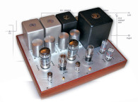
This design takes a different path a single gain stage using a low-mu triode with very low plate resistance (see Photo 2). This achieves the modest gain required along with very low output impedance.
Low-Mu Power Triodes
The output impedance of a grounded cathode amplifier is roughly equal to the plate resistance of the tube in parallel with the plate load resistor. You need to make the plate load resistor large relative to the plate resistance to get low distortion. So, to get low output impedance and low distortion, you need a tube with a low plate resistance.
A number of large power triodes have low plate resistance (Rp), such as the 6AS7 and 6080, 5998, 7236, WE421A, 6528A, and 6336A. Most were designed for voltage regulator service; the 7236 (I believe) was designed to drive motors for vacuum-tube computer tape drives!
Unfortunately, at first glance, these tubes don’t look linear. In a normal resistor-loaded, grounded-cathode amplifier, they have high distortion, mostly even harmonics. This distortion decreases with increasing plate load resistance, but a larger resistor means that you need a higher supply voltage. Luckily, there is a way to present a very high load to the plate of the tube without using a big resistor and high voltage power supply — a constant-current source (CCS) load.
Constant-Current Plate Loads
A constant-current source (CCS) plate load uses an active device (usually a tube or FET) that’s connected so that it always wants to supply a constant current to its load, which in this case is the plate of a triode. This provides a very high resistance load to the plate—essentially, a near-horizontal load line.
With a CCS load, the load line that the tube sees is dominated by the current that’s delivered to the load. There are many possible designs for CCS plate loads some very simple (just a depletion-mode FET and a resistor), and some very complex, using both tubes and solid-state devices. If you’re interested in CCS plate load designs, there is a gold mine of info about them on the Internet (see “References” at the end of the article for some places to look).
I experimented with simple designs using an FET and a pentode. They both performed well. I opted for a pentode, partly because I had them— they were simple and performed well in this application and partly because they don’t need a heatsink. Using a tube lets you dissipate the power above the chassis!
One of the problems with using a CCS — especially a tube CCS — is that you need to have substantial voltage across them, especially if the output voltage swing is substantial. With a low-mu power triode preamp, this isn’t too much of an issue; the output swing is only a few volts, and the triode can be happily run at low plate voltage, leaving more of the available power supply voltage to drop across the CCSs.
The Preamp Design
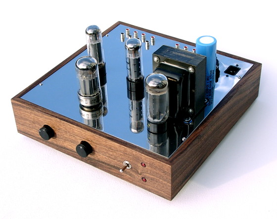
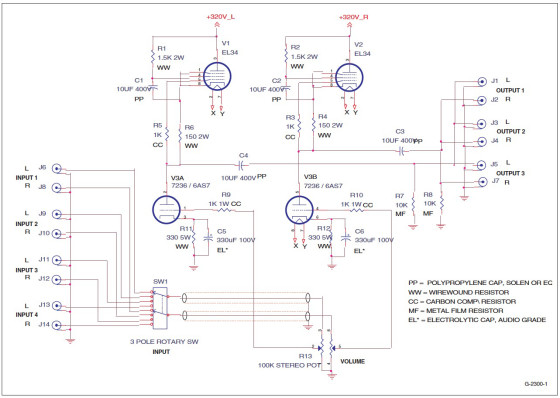
The preamp design is straightforward, using EL34 pentodes wired as CCSs as the plate load for the low-mu triode. The triode tube has two sections, and one is used for each channel. The schematic for the amplifier is shown in Figure 1.
Note that on the EL34 CCSs, the screen grid is bypassed by a large capacitor to the cathode of the tube. A screen resistor is used not so much to reduce the voltage on the screen, but to allow the capacitor to make the screen voltage constant with respect to the cathode.
The current through the CCS (and the triode) is set by the resistor in the cathode of the EL34. The 150-Ω resistor shown sets the stage current at about 50 mA. Note that the grid is connected to the lower end of this resistor, through a grid stopper resistor. This resistor is critical—without it, my amplifier oscillated at 115 MHz, with 100 V RMS on the triode plate!
The triodes are cathode biased with a 330-Ω resistor. With a 7236 tube and a 50mA CCS plate load, this sets the plate voltage at about 125 V. I experimented with different operating points using the 7236 tube, but found that this was about the optimum for lowest distortion. I bypassed the cathode resistors with a good-quality audio electrolytic capacitor.
At first glance it seems as though the cap is not needed, since the plate current is fixed by the CCS; however, the LOAD current still flows through the cathode resistor, and not bypassing it provides some local negative feedback, which reduces the gain somewhat.
In this case (I’m not sure why), it increased the distortion. The triode grids are connected directly to the wiper of the volume control potentiometer. There is a compromise in selecting the volume control resistance: You want a large resistance to achieve a high input impedance, but a high resistance, in combination with the Miller capacitance of the tube, causes a high-frequency rolloff. I used a 250 kΩ pot, and as you can see from the measurements, obtained reasonable high frequency response. You will get better response from a 100k pot, and even better still with a 50 kΩ pot.
I wanted several inputs to be selectable with a switch, so I used a good quality rotary switch to select one of four inputs to feed the volume control.
The output is taken from the triode plate through a polypropylene coupling capacitor. I connected three sets of output jacks in parallel, so I could drive several loads at the same time.

Power Supply
The power supply is conventional, using a tube rectifier and capacitor input filter. I used a 5U4GB rectifier tube, but others would work as well, as the total current draw is only around 100 mA. I used a large second capacitor in the filter, 750 μF, to provide low ripple.
The B+ voltage is between 300 V and 325 V, and in bench tests appears to be not very critical. The audio circuitry is de-coupled from the power-supply filter by using 100-Ω resistors and 47-μF polypropylene capacitors. I believe that this scheme, which keeps almost all of the audio current out of the power-supply filter and instead sends it through the higher quality polypropylene caps, sounds better than relying on the large electrolytic cap in the filter. Filaments are powered with 6.3 VAC, which is biased up to about 45 VDC, derived from the power-supply bleeder resistor.
This bias is needed to stay within the 100-V maximum heater-cathode rating of the EL34 tubes, whose cathodes are operating at around 140 V. It also helps reduce any noise coupling from the triode tube’s filament, by reverse biasing the intrinsic diode formed between the heater and cathode.
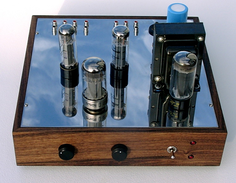
I use the preamp power switch to control the power to my amplifiers, but there are times (such as when using a headphone amp) that I don’t want to power them on but still use the preamp. To accomplish this, I used a center-off DPDT power switch. In one position, power is applied to just the preamp; in the other, power is applied to both the preamp and to an AC receptacle which is used to turn on the power amps. In the center “off” position, both the preamp and power amps are off. Neon pilot lamps are used to show what’s turned on.
In the schematic, you’ll see a metaloxide varistor placed across the power transformer primary. This device is a transient suppressor, and helps to clamp both the line voltage spikes as well as the inductive spike that occurs when you turn the power off. I also used a filtered IEC power input connector to help keep noise out.
The Chassis And Base
I built the preamp using a little different construction method than usual: point-to-point wiring and single-point solder terminals. The chassis top is made up of a sandwich of PCB material and polished stainless steel sheet. The use of single-point terminals, as opposed to terminal strips, allows you to place each end of each component exactly where you want them.
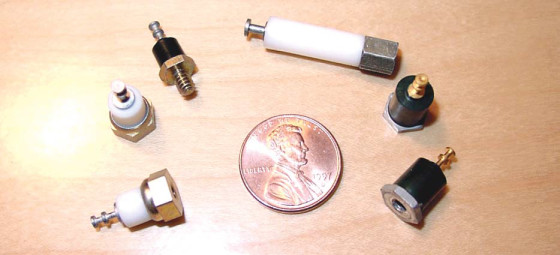
Single-point terminals are used in some mil-spec point-to-point wiring, and are available in a number of shapes, sizes, and styles. Photo 3 shows an assortment of types. I used terminals with female threads, such as the ones at the right side of the picture (refer to the “Parts Sources” section at the end of the article for information on where to get these terminals).
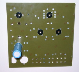
The terminals are fastened to a piece of bare PCB material, using flathead screws that are countersunk flush with the surface. Photo 4 shows the PCB from the top, with the flush screw heads. Other components inside the chassis are mounted to the PCB material the same way.
After I mounted all the terminals, tube sockets, and other components to the underside of the PC board, I attached a thin piece of polished stainless steel over the top, using an adhesive called “3M high-performance transfer tape.” This stuff is no ordinary double-stick tape 0151it’s an acrylic adhesive that forms a permanent bond. The “squishiness” of this material also helps to make the completed chassis acoustically dead.
The stainless steel covers all of the countersunk screws, giving a neat appearance on the outside. The only holes drilled or punched in the stainless are for components that mount on top of the chassis, such as the tubes and transformer. I purchased the polished stainless steel pre-cut in a 12″ × 12″ square from McMaster-Carr.
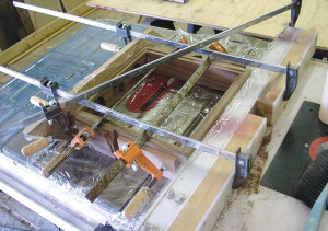
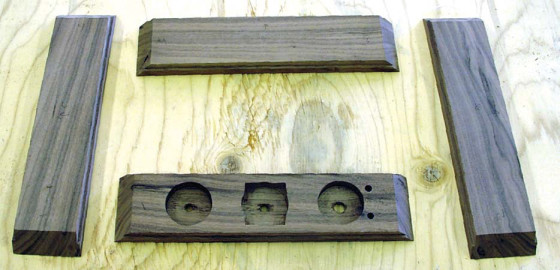
The PCB and stainless-steel sandwich is mounted into a wooden base that I made from walnut. Photo 6 shows the individual pieces of wood cut and ready to be assembled. Note the counter bores on the inside of the front piece to allow mounting the power switch and volume control. I glued the pieces together with a number of clamps as shown in Photo 7. The clamp going diagonally across the base pulls the base into square 0151you need to make sure the base is square, or your chassis won’t fit together!
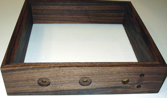
You can see the finished wooden base in Photo 8. The chassis top sits into a step that I routed into the wood pieces before gluing them together. Similarly, an aluminum plate attaches to the underside to form a bottom.
Wiring And Component Installation
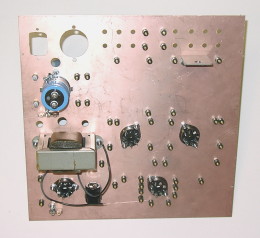
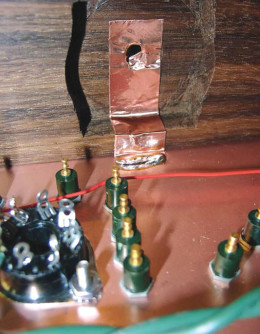
After mounting the chassis “sandwich” into the base, you then install the remaining components (power transformer, RCA jacks, and so on). I used some copper foil tape to provide a ground connection to the volume control from the copper ground plane (Photo 9).
I finished all of the wiring before installing any of the parts, using Teflon-insulated solid wire. This type of wire, though a little hard to strip, is nice to work with, because the solid conductor is easy to wrap around the terminals, and the insulation doesn’t melt from the heat of a soldering iron.
It’s also easy to wrap around the singlepoint terminals and tube sockets without fraying as stranded wire would.
I mounted the input selector switch right above the input connectors on a bracket, and operated it with an extended shaft, to minimize the length of the signal wiring. After wiring, install the leaded components, wrapping their leads around the terminals and soldering.
Adding the parts after the wiring makes it easier to change them after the fact, if you want to try different component values. A view of the inside of the completed chassis is shown in Photo 10.
control grounding.

Measurements
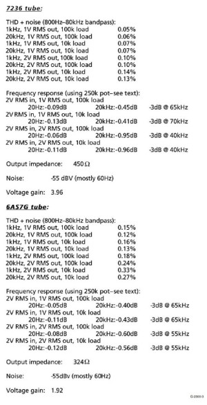
I made a number of measurements (see Figure 3), using both a Cetron 7236 tube and a Russian 6AS7G tube. The measurements included THD, noise, frequency response, output impedance, and maximum voltage gain. In general, there were only small differences between tubes, other than the expected gain difference due to the tubes’ differing amplification factors.
I also performed spectral analysis (FFTs) of the output distortion to check the harmonic content. I didn’t include any pictures of them because they’re not very interesting—the only harmonic that was above the noise was the second harmonic.
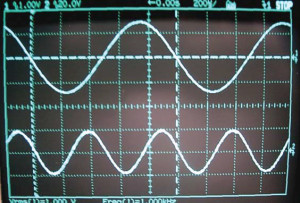
This was true for all of the conditions tested, and for both tubes. Photo 11 shows an oscilloscope picture of the output (top trace) and the distortion residual (bottom trace). The distortion residual, shown at a much higher scale than the output signal, was filtered and averaged to remove all the noise components. You can see that it’s pretty much a pure 2-kHz sine wave.
As discussed, I used a 250 kΩ volume control pot, which is the limiting factor for high-frequency response. Using a lower resistance control will extend the high-frequency response considerably.
(bottom, not to scale).
Listening Impressions
I never thought much about what sonic impact my old preamp (a PAS-type 12AX7 circuit, with lots of negative feedback) was having on my system until I replaced it with this preamp. The biggest difference was in the clarity of high frequency transients. For example, the strike of a bell sounded real, not recorded.
I often don’t like live recordings, because they tend to sound too muddy—there’s so much low-level stuff in the background (such as the audience). This preamp seemed to resolve more of that detail, and live recordings I didn’t like much before came alive. I was pleasantly surprised.
Of course, nothing is perfect. My only complaint is that the tubes are microphonic and a little noisy—especially while warming up. It’s understandable—after all, these are big power tubes, and they weren’t designed as low-noise, low-level amplifiers. After they’ve heated up for a while the noise diminishes, and I suspect some vibration dampers—maybe just a silicone O-ring—would help, especially on the tall, skinny EL34s.
References
www.audioasylum.com − Great Internet bulletin board for all things audio. Check out the “Tube DIY” section for lots of discussion about tube circuits.
www.bottlehead.com − The folks at Bottlehead were one of the first to popularize CCS plate loads. Check out their kits.
www.pmillett.com − The author’s web site, where you can download full-scale drawings of this project.
Parts Sources
McMaster-Carr - www.mcmaster.com
Stainless steel and aluminum sheets, hardware, 3M high-performance transfer tape adhesive
Cambion - www.cambion.co.uk
Single-point terminals (part number 572-4827-01-05-16)
Concord Electronic Hardware - www.concord-elex.com
Single-point terminals (part number 1127-30-0516)
USECO Fastners - www.staffall.com
Single-point terminals (part number 1417)
This article was originally published in audioXpress magazine, February 2004