This is the first time I have examined a transducer from RCF. Italian-based RCF has a rich history that extends back to its founding in 1949 by a group of Italian electro-acoustic engineers. The company initially made microphones, amplifiers, and related products for public-address applications. During the 1950s and 1960s, RCF established itself as an OEM transducer manufacturer. By the mid-1960s, the company had become the first in Europe to have a high-level transducer research center.
In 1996, the company launched the ART series of active composite-molded pro-audio cabinets. This technology — used at the time by only a handful of manufacturers — instantly positioned RCF as a global player in the pro-audio loudspeaker market. In 2004, a new era began for RCF, with fresh investment in research and development and a renewed commitment to manufacturing in Italy. Since then, the company has designed, put into production, and delivered to the market a substantial number of new products every year. Prominent among them is the TT+ High Definition Touring and Theatre Series, which became an instant success thanks to innovative amplifiers equipped with DSP, along with state-of-the-art transducer technology. Starting in July of 2007, RCF Group (the company that comprises RCF S.p.A. and AEB Industriale, which owns the brand dBtechnologies) was listed on the Italian Stock Exchange.
RCF’s ND950 and the HF950
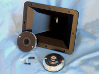
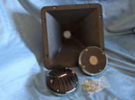
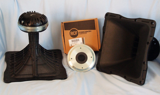
The first driver I received from RCF was the ND950 1.4 neodymium compression driver along with the HF950 injection-molded composite horn specifically designed to work with the ND950 (see Photo 1). The ND950 uses a 0.05-mm thick pure titanium diaphragm coupled to a flat mylar suspension mounted behind a four-slot phase plug. The throat diameter is 35.5 mm (1.4”) with the diaphragm driven by a large 100-mm (4.0”) diameter voice coil wound on a Kapton former with edgewound aluminum wire. Other features include a large neodymium ring magnet, copper shorting ring, 140-W AES-rated power handling (above 1 kHz), 280 W continuous power handling (above 1.2 kHz) and solderable terminals. The horn supplied with the ND950 1.4” driver is RCF’s 1.4” throat 90°-H × 50°-V HF950 constant directivity horn, featuring a 400-Hz cutoff frequency.
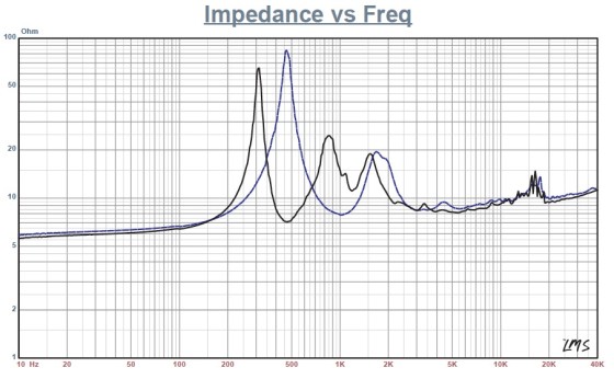
I used the LinearX LMS analyzer to produce the 300-point stepped sine wave impedance plot shown in Figure 1. Note that the solid black curve shows the ND950 mounted on the HF950 horn and the dashed blue curve represents the compression driver without the horn. With a 6.37 ohm direct current resistance (DCR), the ND950/HF950’s minimum impedance in the operating range was 8.13 ohm at 5.5kHz.
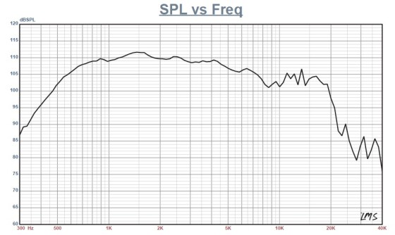
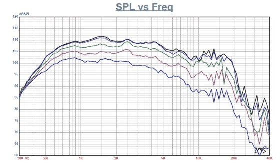
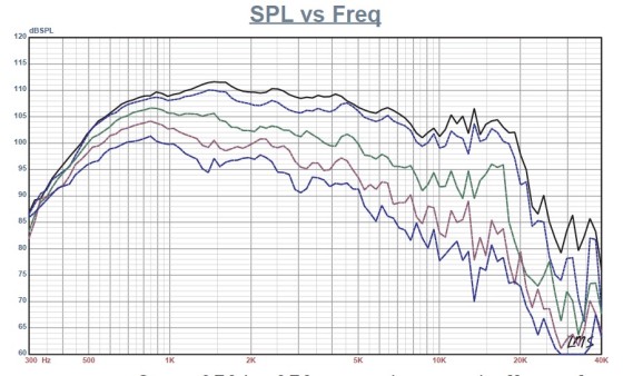
For the next test sequence, I mounted the RCF ND950/HF950 on a rotating platter (no surrounding baffle). I used a 100-point gated sine wave sweep to measure the horizontal and vertical on- and off axis at 2.83 V/1 m. Figure 2 displays the compression driver/horn combination’s on-axis and shows an approximate 112-dB maximum sensitivity. RCF’s rated sensitivity for the ND950 is 110 dB measured with pink noise at 1 W/1 m with a Q of 15 on-axis and averaged between 2 to 5 kHz. The sound pressure level (SPL) profile measures ± 4 dB from 550 Hz to 8 kHz. Figure 3 shows the horizontal on- and off-axis to 60°. The vertical orientation is shown in Figure 4.
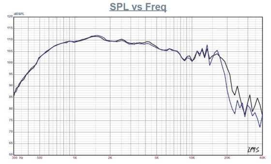
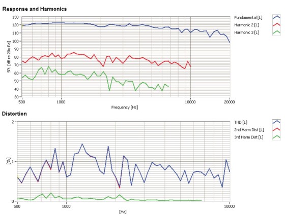
Figure 5 details the two-sample SPL comparison. Both samples appear to be closely matched. For the remaining battery of tests, I set up the Listen SoundCheck analyzer and 0.25” SCM microphone and power supply to measure distortion and generate time/frequency plots. For the distortion measurement, I mounted the RCF ND950/HF950 combination on the same rotating platter used for the frequency-response measurements. I used a pink noise stimulus to set the SPL to 104 dB at 1 m (0.62 V). Then, I measured the distortion with the Listen microphone placed 10 cm from the horn’s mouth. This produced the distortion curves shown in Figure 6. I used SoundCheck to get a 2.83-V/1-m impulse response and imported the data into Listen’s SoundMap time/frequency software.
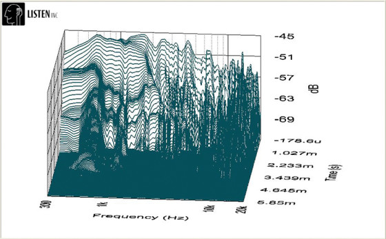
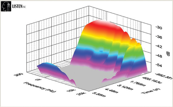
Figure 7 shows the resulting CSD waterfall plot. The short-time Fourier transform (STFT) plot is shown in Figure 8. The RCF compression driver’s build quality is impressive, as you would expect from an established pro sound company. For more information, visit www.rcf.it
This article was originally published in Voice Coil, April 2013.