 I designed my sound level meter and spectrum analyzer, the Model 527, around a Velleman Audio Analyzer kit (K8098). It is a barebones kit with no enclosure or power supply, but for the price, it is very versatile. I found it easy to build and thought it would be useful in a project. It comes with a 15-page assembly manual and a user guide, which can be downloaded from the Velleman website.
Originally published in audioXpress, December 2013
First, I will review the specifications so you will know what the audio analyzer kit can do. It has a front-panel push-button Mode switch with six selections: Peak power, RMS power, mean (or average) voltage in decibels (dB), peak voltage in dB, linear audio spectrum (20 Hz to 20 kHz) and one-third-octave log audio spectrum (band centers from 31 Hz to 16 kHz). Its sensitivity is –34 dBu which is equal to 15.5 mV RMS. More importantly, it has a 40 dB dynamic range, which means the voltmeter modes have a 15.5-mV-to-1.55-V (–34 to 6 dBu) RMS and peak range.
(The voltage and spectrum analyzer modes have the same dynamic range.) The LCD shows the input as a bar graph and as numeric values. It also has a Setup Menu (a “long” press on the Mode switch) for language selection, auto, or manual range selection, display contrast, and so forth. The only specification that I may dispute is the “easy panel mounting,”but I will discuss that in more detail later.
A Sound Level Meter
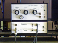
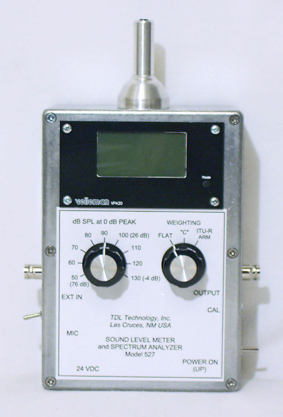
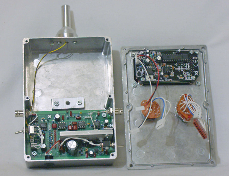
To convert the kit into a useful test instrument, I designed and built a sound level meter (see Photo 1). I opted to call my design the Model 527, because I wanted to keep track of all the drawings and photos. (It may or may not be a TDL Technology product.) The cast aluminum enclosure measures 6.73” × 4.76” × 2.17.” An addendum with full-size drawings, more photos, a parts list, and wire lengths is available at www.tdl-tech.com/build527.htm. A 24-VDC wall power supply—or an external battery pack for operation away from power mains—powers the sound level meter. The Velleman kit uses enough power (75 mA) that I think internal batteries are not practical.
It has a built-in electret condenser microphone (ECM) and an external input to a female Bayonet Neill–Concelman (BNC) connector as selected by a left-side mounted toggle switch. The external input impedance is 47 k and it is DC coupled.

The sound pressure level (SPL) front-panel rotary switch is numbered 50 to 130 dB in 10 dB steps. This is the measured SPL when the graphic display MODE is set to “Peak dBu-Meter” and the reading is 0 dBu. But at each switch position the display has a 40-dB range (–34 to 6 dBu) so the overall SPL range is 16 dB (50 – 34 on the lowest range) to 136 dB (130 + 6 on the highest range). The useable range is about 30 to 136 dB because of the inherent noise in the amplifier circuit. Although the display label is “Peak,” the reading is the mean or average SPL. The spectrum analyzer amplitude value is the same as the displayed SPL.
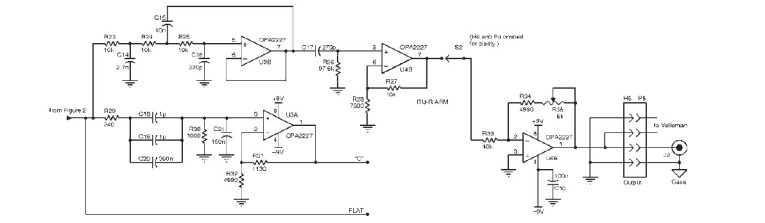
There are three frequency weighting responses as selected by a front-panel rotary switch: FLAT, “C,” and ITU-R ARM. The flat response is ±1 dB from 20 Hz to 20 kHz and is primarily set by the microphone cartridge rather than the amplifier. The “C” response attenuates the low and high frequencies (see Figure 1). Its use is still favored for subjective sound measurements especially at high SPLs. The old “A” and “B” responses were found to be generally unsuitable in practice and the ITU-R ARM is suggested as a replacement for both. Figure 1 also shows its frequency response.
The approximate voltage gain from the external input is shown on the SPL range switch. It increases 10 dB for each switch step position as the SPL range decreases. This gain value is approximate because the microphone sensitivity varies slightly from unit to unit and depends on the Calibration control’s setting: a 20-turn variable resistor accessible through a small hole in the enclosure’s right-hand side.
The signal to the Velleman analyzer also goes to a female BNC connector on the enclosure’s righthand side. It could be useful for driving an oscilloscope or another instrument (e.g., a computer sound card). Tripod mounting is provided by a 0.25”-20 threaded insert near the center of the enclosure’s bottom side.
The Circuit
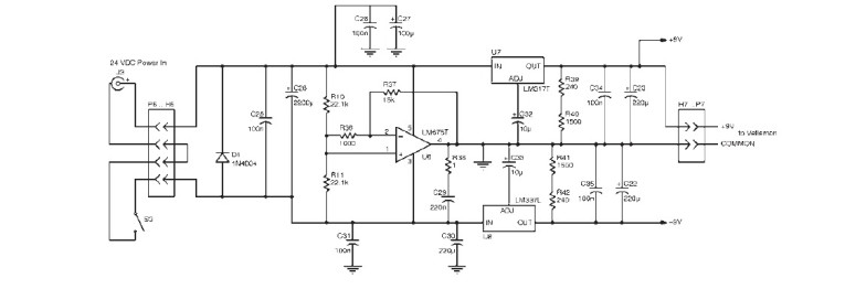
The input amplifiers, microphone bias voltage, frequency weighting networks, and power regulators are on a single circuit board measuring 4.5” × 2.7.” This is the largest board that will fit in the enclosure’s lower half so the electronics are rather compact.
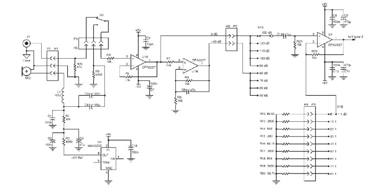
Figures 2–4 show the circuit diagrams. These figures and the parts list only apply to the added amplifier and filter circuits on the Model 527’s main board. The Velleman analyzer’s circuit diagram and parts list are included in its User Guide.
The microphone cartridge is a modified Panasonic type WM-61A for better linearity at higher SPLs (see Figure 5). Working on this small cartridge is easier if you drill an 0.125” deep, 0.242” diameter (a “C” drill) hole in a hardwood block to serve as a holder. Also, roughen the cartridge’s outside surface with a small file because it must be glued into the microphone holder with conductive epoxy or Wire Glue. A good electrical contact with the holder is essential for mechanical stability and low-noise operation. The Velleman User Guide calls for operation from a 12 VDC power supply. It is regulated down to 3 to 3.6 VDC on the circuit board, so my ±9 VDC power supply is fine.
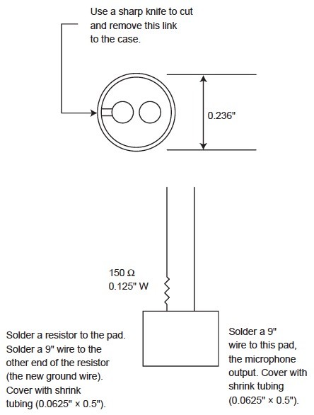
for better linearity at higher sound pressure levels (SPLs).
Construction
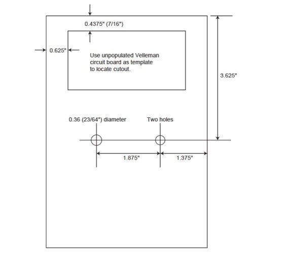
Mounting the completed Velleman kit is not as easy as its assembly manual claims. The cutout shape is a rectangle with the corners cut off. Use the circuit board as a template before starting the assembly (see Figure 6). Most of the cutout can be removed with an 1.5” diameter hole punch or hole saw. Punch or saw two overlapping holes in the cutout area and then remove the rest of the material with a file. The enclosure is made of a cast-aluminum alloy and it files rather easily. I made this cutout in three top plates in a little more than an hour total. One caution if you use a hole saw to get started: Stop sawing frequently and let the saw cool or it will melt enough of the alloy to clog the saw teeth.

enclosure’s bottom. It is better to use an unpopulated circuit board as
a template to locate its mounting holes in the enclosure’s lower half.

of the meter enclosure.
Figure 7 shows the tripod mount detail but it’s better to use the Model 527’s circuit board as a template to mark its mounting holes. Place the board, component side up, in the lower half of the enclosure and mark through the holes. (Do not mark through the two 0.14” holes inside the white rectangle. These are used to attach the heatsink bar to the board.) There are three 0.125” diameter holes for the 4-40 × 0.375” machine screws. Put the screws in the holes and secure them finger tight with 4-40 nuts. Do not fully tighten them yet.
Put the circuit board in position and then finish tightening the nuts. Before you mount the completed board, place a #4 nylon washer on each of the three screws between the nut and the board. To complete this process, secure the board with three more 4-40 nuts.
Figure 8 and Figure 9 show the holes to be drilled in the enclosure. In addition to the published drawings, refer to the full-size drawings, circuit diagrams, parts list, construction photos, and connector and switch wire lengths posted online. See the Resources and Sources sections at the end of the article.
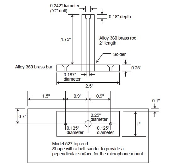
I built two versions of the microphone holder: the shaped-aluminum type shown in Photo 1 and the “tube and bar” design shown in Figure 9. Performance is essentially the same and the Figure 9 design is much easier to build.
The cast enclosure has slightly outward sloping walls for good mold release but this means the microphone holder surface is not perpendicular to the enclosure top and bottom. This is easily fixed with a belt sander. Sand off enough of the enclosure’s microphone side to make the top half perpendicular to the enclosure bottom. Sanding just the top half is sufficient, and it prevents you from making that wall too thin.
The new ground wire from the microphone connects to a solder lug under the left-side of the microphone holder mounting screw as shown in Photo 2. Another wire continues from this lug to the common connection at H1 on the circuit board.
Calibration
To calibrate my Model 527, I used a Tenma Sound Level Calibrator (model 72-7260) from MCM Electronics. This is a fairly inexpensive unit that generates a 1,000-Hz tone at an SPL of 94 dB (1 Pa). It is built for a 0.5” diameter microphone, which is one of the industry standards (along with 0.25” diameter) and its size dictated my choice of a 0.5” diameter holder.
Another option is to calibrate by comparison using another sound level meter. Just closely place the two meters side-by-side at least 3’ in front of a loudspeaker and play a 1,000-Hz low-distortion tone at an SPL between 90 and 100 dB. Adjust the Model 527’s calibration control to match the reading on the other meter.
If you have a measurement microphone (e.g., the Dayton EMM-6) you will have a calibration graph that shows the sensitivity at 1,000 Hz. It will be around 10-mV RMS at 1 Pa or 94 dB SPL. With a microphone preamp having 40-dB gain, you will have a 1-V RMS output at 94 dB SPL. Using a test oscillator and loudspeaker, you can calibrate the Model 527 by comparison to the microphone’s output.
Performance
The amplifier noise level referred to the input is 10- to 12-V RMS depending on the weighting switch setting. This means the meter’s useful range is about 30 to 136 dB SPL. To put this range into perspective, a quiet office has an ambient noise level of about 40 dB SPL and a jet engine at 100’ has an approximate 140-dB SPL. An Internet search will provide various SPL tables for different environments. Overall, the Model 527 seems to perform well for the effort it takes to build it. The parts cost approximately $110, plus the Velleman kit. It may cost less if you already have some of the parts on hand.
About the Author
Ron Tipton has degrees in electrical engineering from New Mexico State University and is retired from an engineering position at White Sands Missile Range. In 1957 he started Testronic Development Laboratory (now TDL Technology) to develop audio electronics. He is still the TDL president and principal designer.
Resources
Velleman, www.vellemanstore.com
All Electronics, www.allelectronics.com
Jameco Electronics, www.jameco.com
Marlin P Jones Associates, www.mpja.com
Mouser Electronics, Inc., www.mouser.com
Parts Express, www.partsexpress.com
TDL Technology, Inc., Addendum with full-size drawings, more photos, a parts list, and wire lengths,
www.tdl-tech.com/build527.htm
Velleman, “K8098 Audio Analyzer Assembly Manual” 2012,
www.vellemanusa.com/downloads/0/illustrated/illustrated_assembly_manual_k8098.pdf
Sources
K8098 Audio analyzer kit: Velleman | www.vellemanstore.com
Tenma 72-7260 sound level calibrator: MCM Electronics
Microphone holder brass and aluminum: McMaster-Carr | www.mcmaster.com
Dayton EMM-6 measurement microphone: Parts Express | www.parts-express.com
527 Circuit board and microphone holder: TDL Technology | www.tdl-tech.com/parts527.htm