By Nick Soudas
I grew up listening to solid-state equipment, having been born too late to catch the tube wave. During my formative years I read about vacuum tubes, but always dismissed their use in audio, since the mighty transistor was far superior. After building a 2A3 single-ended (SE) amplifier and retrofitting a set of 300Bs in place so I could compare the two types of output tubes, I was amazed at what a SE directly-heated triode (HT) amplifier could sound like.
I can now honestly say that I prefer vacuum tube amps (although I like tinkering with all types of audio gear). After the 2A3/300B project I wished to take the SE DHT concept to the next level and use a different output tube. As with most hobbies (or electronics, for that matter), it’s not difficult to find the next level.
Output Tube
While surfing the Internet and reading various periodicals, I noticed “big power triodes,” namely, the 211/845 family. Even though Svetlana has a current line of power triodes (572 and 811 series), I was curious about the older American triodes. Supposedly, for the ultimate SE DHT sound, these were the tubes to use.
The 211 was originally designed in the early ’20s, deriving its heritage from an earlier tube used during WWI in Navy radio transmitters. If you compare the plate characteristics of DHTs, such as the 2A3 or the 300B, the 211/845 family is much more linear. Of course, this linearity has a price: a high plate voltage.
I had three goals in mind when I started this project. First, I wanted to design a direct-coupled input/driver circuit that would provide the proper drive voltage to the grid of the 211. Second, the circuit had to be simple (for sonic reasons), but able to supply the full drive voltage to the 211 grid. Third, I wanted to keep construction simple (for building purposes), to encourage other do-it-yourselfers to try a 211-based amplifier. I came across a few designs using 211 and 845 transmitting tubes. Some of the designs used choke loaded plates, while others used transformer coupling between voltage gain stages.
All the designs had at least two gain stages. I found this unusual since the 211 grid needed only about 150V p-p, which is moderate. After tossing around the idea for a while, I decided to use one of my favorite circuits — a voltage amplifier direct-coupled to a cathode follower. I chose to use new Chinese 211 tubes to test my design, and then retrofit some NOS American 211s (Photo 1).
Input/Driver Stage
I have always preferred octal preamp tubes instead of the miniature glass type. Every project I have built in the past few years has used at least one 6SN7 or 6SL7. The plate curves for these octal tubes are very linear. Initially, I wished to use the 6SL7 in a shunt regulated push-pull (SRPP) configuration to get maximum gain, but since the heater-to-cathode voltage is only 90V, I was unable to use the SRPP topology with a high plate voltage. Typically, a SRPP stage will have half of the plate voltage on the upper cathode.
To see why I was unable to use the SRPP stage, assume a plate voltage of 430V. If both cathode resistors are the same (1kΩ), then I should have about 215V on the upper cathode with reference to ground. If I bias the heater on the 6SL7 to 90V (maximum rating according to data), then I still have a 125V difference between the upper cathode and the heater.
Although the 6SL7 could probably handle the voltage difference, I was concerned about not stressing the tube to ensure that the circuit operated well within ratings for a long, trouble-free life. Since I wished to use the 6SL7, I pondered other ways that I might use it. I finally decided to parallel both triode sections of the 6SL7 to lower the plate resistance, and to get a better noise figure.
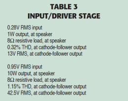
While experimenting with the plate curves for the 6SL7, I discovered that, with a plate voltage of 435V, I could easily get about 150V p-p. The input/driver stage load line exhibited .32% THD at 13V RMS output. This voltage output coincided with 1W output to the speaker.
The input stage distortion could be lower, but later I’ll explain how I reduced it to extremely low levels. The output stage clips before the input/driver circuit, which, in my opinion, is the way an amp should behave.
While paralleling both sections offers some advantages, there is also a disadvantage; the shunt input capacitance doubles too. I was concerned about this at first, but after some frequency-response measurements of the input/driver stage, the bandwidth seemed in order. The actual input/driver circuit (not connected to the 211) swings 153V p-p (54V RMS) with a bandwidth from 10Hz (down −0.53dB) to 90kHz (down −3.0dB).
The 6SL7 has some cousins, which you should not overlook, the 12SL7, 7F7, and 14F7. Sylvania manufactured the 7F7 and 14F7 to gain some market share from RCA, who produced the octal-type tubes. Except for the different type of base, the Sylvania tubes are identical electrically to the RCA octals.
Instead of using an octal base, Sylvania Sylvania had a Loktal base; that is, an octal base with a lock-in feature. The Loktals had eight pins, but they were much smaller than the octal type. Any of these 6SL7 derivatives will produce excellent sonic results.
The cathode-follower section is direct-coupled to the input stage for low phase shift and stability. A 6J5, 6C5, 6P5G, or a 6SN7 would have worked great in this section, but I preferred to use a shoulder-type tube for aesthetic reasons. The 6F8G is very similar to the 6SN7 family of tubes; it has a shoulder type bulb (which I think is more nostalgic-looking), and its internal capacitance is slightly different.
Plus, I wished to parallel the triode sections (for more driving current) to ensure that the 211 grid capacitance would not load down the cathode follower.
Power Supply
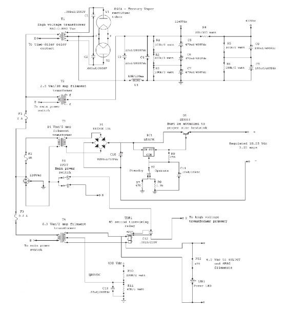
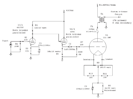
The power supply for this amplifier (Fig. 1) may seem very complex at first, but, if you break it down into three basic sections, it does not seem that daunting:
1. Main B+ high voltage/rectifier filaments/time delay
2. 211 filament
3. Input/driver filament
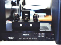
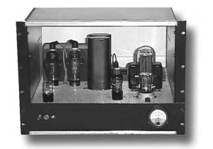
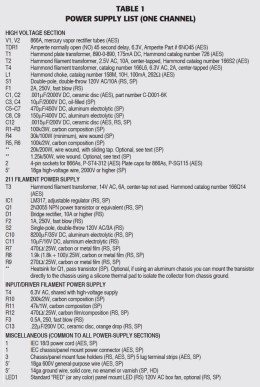
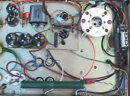
Table 1 shows the power-supply parts list. Ironically, although the amplifier circuit is very simple, the power-supply turned out to be a monster. It occupies two-thirds of my chassis (Photo 2).
for the 6SL7 and 6F8G. Time-delay relay
(upper-left corner). Part of amplifier section (top-right corner).
This was my first time building a power supply of this type and magnitude. While the voltages in the power supply are quite high, do not be discouraged, just take a little extra time and be extremely careful when working around the power-supply section. The 211/845 family of power tubes can operate with 1250V on the plate. Anything over 1000V is enough to improve the tubes’ sound, in my opinion.
The tube is rated at 75W, which seems rather low given the size of the plate. Early 211s had a stamped plate, and later ones utilized a graphite-type plate. The Chinese tubes were modeled after the later American tubes, so they all have (carbon) graphite plates. The older American tubes (with graphite plates) can probably handle a 100W plate dissipation, but I doubt the Chinese clones can.
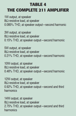
Running the tubes at 1000V/60mA produces a power dissipation of 60W, which is less than the rating, so tube life should be extended. With this combination of voltage and current, I realize around 14.5W/channel from my amplifier at 3% THD. I used a “pi” input filter directly after the 866As.
The first capacitor is a 10μF/2000V DC oil capacitor, followed by a Hammond choke rated at 10H/100mA, and then another 10μF/2000V DC oil capacitor. Initially this input filter yielded good results, but a little hum was noticeable on the output, so I added additional capacitance in parallel to the second oil capacitor. Since I couldn’t find a high capacity/high voltage capacitor locally, nor could I afford an adequate oil capacitor, I reluctantly used aluminum electrolytic capacitors… after convincing myself that it is perfectly acceptable to mix and match capacitors (for that sonic flavor).
The Hammond choke has a voltage rating of 400V DC. Not wishing to risk voltage breakdown of the choke, I used “negative lead” filtering. This is very common with higher voltage power supplies. My B+ high-voltage ended up being 1140V DC, with a current draw from the amplifier of about 85mA. The Radio Amateurs Handbook, published by the American Radio Relay League (ARRL), 35th edition — or any edition around the late ’50s or early ’60s — contains much information regarding tube power supplies.
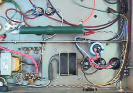
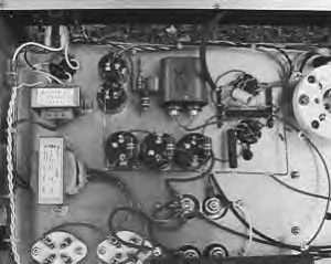
Transformer, rectifier, and filter capacitor
(bottom right).
and power-supply section.
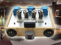
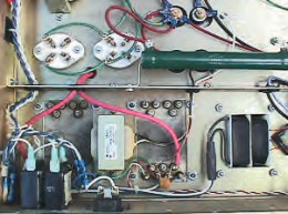
Mercury vapor tubes/sockets
(upper-left corner).
Voltage divider resistor for input
tube section (big resistor in center).
211 filament transformer (bottom right).
front panel controls.
Power indicator, far left.
Switch next to power indicator is
the main power switch.
Far-right switch is the 211 filament
“operate/standby” switch. Righthand side
of panel, contains an optional
current meter to monitor 211
output tube current.
After obtaining all the power-supply components, I temporarily connected everything on a piece of wood (18″ × 18″ piece of pine) to test, measure, and work out any bugs in my paper design.
You must be careful to choose wire with the correct voltage rating in the high voltage section. I used wire with a rating of 3,000V because this is what I had on hand, but you can use anything with a rating of 1,500V or higher.
The secondary of the high-voltage transformer needs to be 900-0-900/200mA, or close to this, for a full-wave capacitor input supply. Power-supply design is as hotly debated as amplifier design itself. I believe that if you are going to go through the trouble of designing and building a tube amplifier around modern components (or even NOS parts, for that matter), a tube-based power supply is the only logical choice. It is not as simple or inexpensive as a solid-state supply, but I think the extra money and effort are worth the sonic benefits.
The 211 filament power supply (Photo 3) is regulated DC. An LM317 adjustable IC regulator drives an external NPN pass transistor. The external pass transistor is necessary because the LM317 has a current rating of only 1.5A.
The 211 tube requires 10.25V/3.25A AC or DC on the filaments. When I built my 2A3 amplifiers, I initially used AC on all the filaments and was surprised to find hardly a trace of hum on the output. When I retrofitted the 300Bs, I decided to use regulated DC on the filaments because I did not have a 5V AC filament transformer. With DC on the output tube filament only, and AC on the input section, the slight hum previously present was now gone.
In keeping with my simple design philosophy, and having had good results in the past, I used AC on the input/driver filaments. 211 tubes that operate continuously seem to have a lower mortality rate than those frequently turned on and off.
Apparently, this is due to the high in-rush current of the tube filament (and consequently, the rapid heating and cooling of the filament when it is turned on/off frequently contributes to the filament literally “breaking” in half as if bending a piece of metal back and forth until it breaks).
I decided to incorporate a standby switch for the 211 filament circuit. It has two operating modes: standby and operate. In the “standby” mode, the filament is just barely glowing orange. When switched to “operate,” the filament gets full operating voltage.
Mercury Vapor Rectifiers
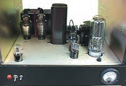
Being limited by the limited number of available tube rectifiers that could handle high voltage, I finally settled on using 866A mercury vapor (MV) rectifiers (Photo 4). The 866As can handle up to 10,000V and fairly high current surges (briefly). Mercury vapor types must be treated differently than other tube-based rectifiers.
If they have been turned upside down or the mercury inside has been spread all over the inside of the bulb (if you mail-ordered your tubes do not omit this step), you may wish to connect filament voltage (no plate voltage) for about 10–15 minutes and let the mercury vaporize inside the tube.
Afterward, make sure the tube is supported in an upright position until you can insert it into the circuit. This precautionary step will minimize arcing and flashover. Also, the MV tubes must be “pre-heated” before they can be used in a circuit.

Typically, when the tube is upright, a small amount of mercury will collect at the bottom of the tube base. A “preheat” time is required to vaporize the mercury (raise the temperature of the condensed mercury) before the tube can start to conduct current. If the temperature inside your home is at least 70°, then a 45–60 second warm-up time should be sufficient.
I used 45-second Amperite “normally open” (NO) time-delay tubes in the power supply with no problems. Of course, these times are temperature dependent; if the tube is extremely cold a longer pre-heat time will be required to “vaporize” the mercury inside the bulb. Since the temperature inside most homes is fairly stable, it would be safe to assume 45–60 second pre-heat time to be adequate for most projects.
If extreme temperatures are encountered, the RCA data sheet for an 866A has good information about operating temperatures. The 866A’s filaments require 2.5V/5A AC for operation. A 2.5V/10A center tapped transformer is needed for the two 866As’ rectifiers. This is a common transformer, so you should not have any trouble locating one for this project.
and part of the power supply.
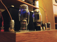
211 tube (top right corner).
6SL7 and 6F8G input section (top center).
Bias resistor and bypass capacitor
mounted to side of chassis (right center).
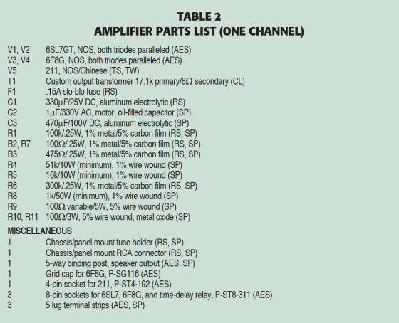
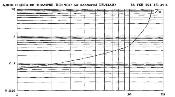
After powering the amp up for the first time (Photo 5), I made measurements to verify operating points and such. (See the amp circuit in Fig. 2 and the parts list in Table 2.)
I used the following test equipment:
Fluke 87 DMM
Old GE analog 2kV DC panel meter
HP 334A Distortion Analyzer
Instek 20MHz Dual trace O-scope
Sound Technology low distortion
1400A Oscillator
B&K 80MHz frequency counter
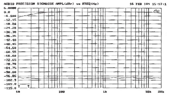
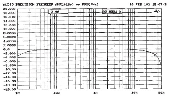
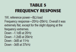
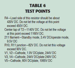
Table 3 shows measurements for the input/driver stage; Table 4 for the complete amplifier; Table 5 for the frequency response; and Table 6 for test points. Figures 3–6 confirm measurements for power, distortion, and frequency.
Output Transformer
Since the 211 has a high plate resistance, I knew that my selection of output transformers was going to be limited. Most, if not all, of the commercial transformers for 211-type amplifiers are about 10kΩ primary impedance. I plotted a 10kΩ load line for the 211, and it looked pretty good.
Next I plotted a 12kΩ load line, and it looked even better. I finally settled on a primary load impedance of 16k for the 211, which yielded very low distortion. As the primary load impedance went up, distortion came down, and power output decreased only slightly. After crunching all the numbers I asked myself “Where am I going to get a transformer with that high a primary impedance (not to mention good frequency response)?”
While looking on the Internet for some NOS 211 tubes, I came across a website called Chimera Laboratories (ChimeraLabs.com). I called and asked about the selection of NOS tubes, and, in the course of our conversation, my home brew 211 amp came up. Dennis Boyle (proprietor of Chimera) mentioned that he had custom transformers available for the 211 tube. He said most of the commercial ones had too low a primary impedance for the 211.
Dennis said the optimum plate load for a 211 was approximately 17kΩ — not far off from what I had calculated. I ordered a set of transformers from Dennis, and about eight weeks later I was in business (a long eight weeks).
Listening to these new transformers was amazing. I really had doubts about the high primary impedance, but they sounded wonderful. Next came time to collect more data from my test bench.
As you read earlier, the distortion and frequency response are respectable. The reduction in distortion, when both input and output stages are cascaded, is a result of second-order cancellation within the amplifier. It would seem that the 6SL7 and the 211 are a good match for each other, with the load lines chosen for each stage.
According to Dennis, the output transformers have the capability (with the proper input/driver circuit) of going up to around 70kHz. I might try a new input/driver circuit in the future, but for now I’m going to listen and enjoy some music for a while.
Construction
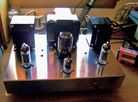
The main chassis for my amplifiers are modified 19” rack-mount computer monitor enclosures (surplus enclosures with a 17” × 17” × 3” footprint). If you are going to build mono amplifiers, I suggest you use this size chassis, which will allow you to position the power supply section well away from the amplifier section so electromagnetic fields will not couple and interfere with each section (Photo 6).
If you decide to build a stereo amplifier, I suggest building the power-supply and the amplifier sections on separate chassis. I suggest this arrangement mainly for convenience. This amplifier gains weight very quickly, and you really won’t care to haul it very far to your workbench. If you’re building a stereo version, I still suggest at least a 17 × 17 × 3 chassis.
Build the power supply first. Start with the high-voltage section, which is the most critical part of the amplifier. The plate voltages specified on the schematic should not deviate more than ±20V. A lower voltage will limit your maximum output power. A higher voltage will cause some of the components to operate closer to their design limit.
After assembling the high-voltage section (T1, T2, V1, V2, C1, C2, C3, C4, L1), connect a 20k/200W load resistor with a sliding tap (centered on the resistor) from the output of the supply to ground. Do not connect the rest of the power-supply components at this time.
Apply power to T2 for only about one minute. After one minute connect T1. The mercury vapor tubes should glow a purple/blue (to see the glow you must be in low light conditions). The mercury vapor tubes will only glow if there is a load connected. If you hear any “loud buzzes or pops,” disconnect power immediately.
If you have a digital meter that can measure DC voltages higher than 1300V DC, then skip the following section and proceed to measure the output voltage. For those of you with meters that go only to 1000V DC, proceed with the following.
With the sliding tap on the power resistor centered on the resistor, measure the voltage from ground to the tap only, then from the tap to the power supply output. Do not measure the full output voltage across your meter, or it may be the last voltage it measures.
Add these two voltages together for total output voltage, which should be between 1150 and 1250V DC. If it is within ±20V of 1150, you are O.K. If it is closer to 1250, then you will need to have to add a power resistor to the center-tap of T2.
Disconnect the center-tap of T2 from C3. Insert a 1250Ω/50W wire-wound resistor between the center-tap and C3. This resistor should bring your output voltage down closer to the 1150 range.
A little patience and experimenting will be required here, so take your time. When the output voltage is in the 1150 range, add the rest of the high voltage components to the supply, making sure to discharge the capacitor through a suitable resistor before proceeding.
With the main B+ voltage correct, everything else will fall into place. This is the most critical part of this project. The filament sections are fairly straightforward.
The main DPDT power switch (S1) performs two functions. It applies power directly to T1, while T2 is time-delayed for 45 seconds through TDR1. After 45 seconds TDR1 closes and sends power to T1, thus energizing the plates of the 866As. When S1 is opened it disconnects T1 and T2 immediately.
The amplifier section is very simple, but effective. The only adjustment is in the 211 filament circuit. Measure from ground to each side of the 211 filament with your meter. Adjust R9 until the voltage on the filament is nearly equal (+5V, 0, −5V). The bias on the 211 cathode should be around 60V DC. Since there is a 1k resistor in the cathode circuit, whatever voltage you measure across the resistor will also be the current through the resistor and through the output tube.
As an option, you can install a 120V AC fan on top of or underneath the chassis to provide some means of ventilation (a small box fan similar to one in a computer). The 1k/50W 211 bias resistor and the 30k/100W voltage divider resistor become fairly warm. Providing ventilation will enhance long-term reliability. Do not connect a 12V DC fan to the 211 filament circuit; this could inject noise into it. These small DC fans have switching power supplies inside them, which generate all kinds of trash that must be filtered out. aX
Original Part Sources
AES—Antique Electronic Supply, 6221 S. Maple Ave., Tempe, AZ 85283, 480-820-5411
www.tubesandmore.com
SP—Skycraft Parts and Surplus, 2245 W. Fairbanks
Ave., Winter Park, FL 32789, 407-628-5634
www.skycraftsurplus.com
CL—Chimera Laboratories, Dennis Boyle, 1707
South Ervay, Dallas, TX 75215, 214-428-3901, Fax:
214-426-6605
www.chimeralabs.com
TS—thetubestore.com, 877-570-0979
www.thetubestore.com
TW—Tube World, 2712 Superior Ave., Sheboygan, WI
53081, 920-331-3126
www.tubeworld.com
About the author
Nick Soudas has worked in the mobile electronics field since the early ‘80s (then in its infancy). He received formal electronics training in the Army and is still active in the Reserve. Currently, he is employed by Jensen Mobile Electronics as part of an electronics design team, designing, testing, and evaluating current/new products/technologies. His main focus is amplifiers and signal processor design. When not tinkering with electronics, he likes to build and fly remote-control airplanes.